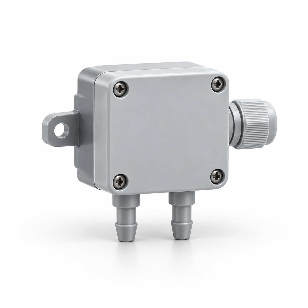
Differential-pressure sensor
The sensor provides a differential-pressure signal for the selected control scheme. The result depends on the pressure points and measurement range.
Two air paths provide coordinated supply and extraction. Their balance, separation and control are selected together; heat recovery is an additional function.
A supply-and-extract unit combines two air paths in one coordinated assembly. The flows are selected to meet ventilation and room-pressure requirements; equal nominal flows do not by themselves establish a balanced building.
The assembly may include heat recovery, but having two fans does not prove that it does. Check air-path separation, intake and discharge positions, leakage, control interaction and access to both sides.
Specify both airflows at their own external pressure, including normal, reduced and boost modes. Pressure relationships may deliberately require unequal flows. Allow for other extract systems and leakage through the building. Commission both paths together; a common speed signal does not guarantee a stable flow ratio when filters load differently.
Related components: Air filter
Calculate one air stream at a time. This calculation does not balance supply and extract or match both air paths.
Calculate sensible air loadCalculate the heat rate associated with a specified temperature change in one air stream. Enter all five values for your stated operating conditions.
Mass flow ṁ = ρ × V̇ / 3600; temperature change ΔT = Tout − Tin; sensible heat rate Q̇ = ṁ × cp × ΔT. With the units below, the result is in kW. Positive Q̇ means heating; negative Q̇ means cooling. Zero flow or zero temperature difference gives zero sensible load.
For a steady, single-phase air stream with constant user-supplied properties. The balance excludes latent heat, moisture changes, phase change, shaft work and kinetic/potential energy changes. It does not select a fan, coil or complete AHU.
Interactive calculation requires JavaScript. The formula, units, scope and reference information remain available here for manual use.
This browser cannot retain the local inputs. They remain available until this page is left.
For a steady, single-phase air stream with constant user-supplied properties. The balance excludes latent heat, moisture changes, phase change, shaft work and kinetic/potential energy changes. It does not select a fan, coil or complete AHU.
The draft contains the topic, entered parameters, method, result, assumptions and unanswered questions. It remains in this page and is not sent.
Choose a topic explicitly to prepare a local draft.
In a combined supply-and-extract unit, recovery uses the two available paths. Select the exchanger and fan pressure duties together. During frost or bypass modes, check what happens to room ventilation and pressure; a recovery controller must not silently defeat the specified airflow regime.
Related components: Fan · Controller
Measure both sides during commissioning and after filter or control changes. Check frost and fault modes for their effect on building pressure. Maintenance records should distinguish supply and extract filters, fan settings and sensor locations so readings cannot be attributed to the wrong path.
Related components: Fan · Air filter
The sensor provides a differential-pressure signal for the selected control scheme. The result depends on the pressure points and measurement range.
A guide to equipment and selection; the final configuration and performance require project-specific confirmation.