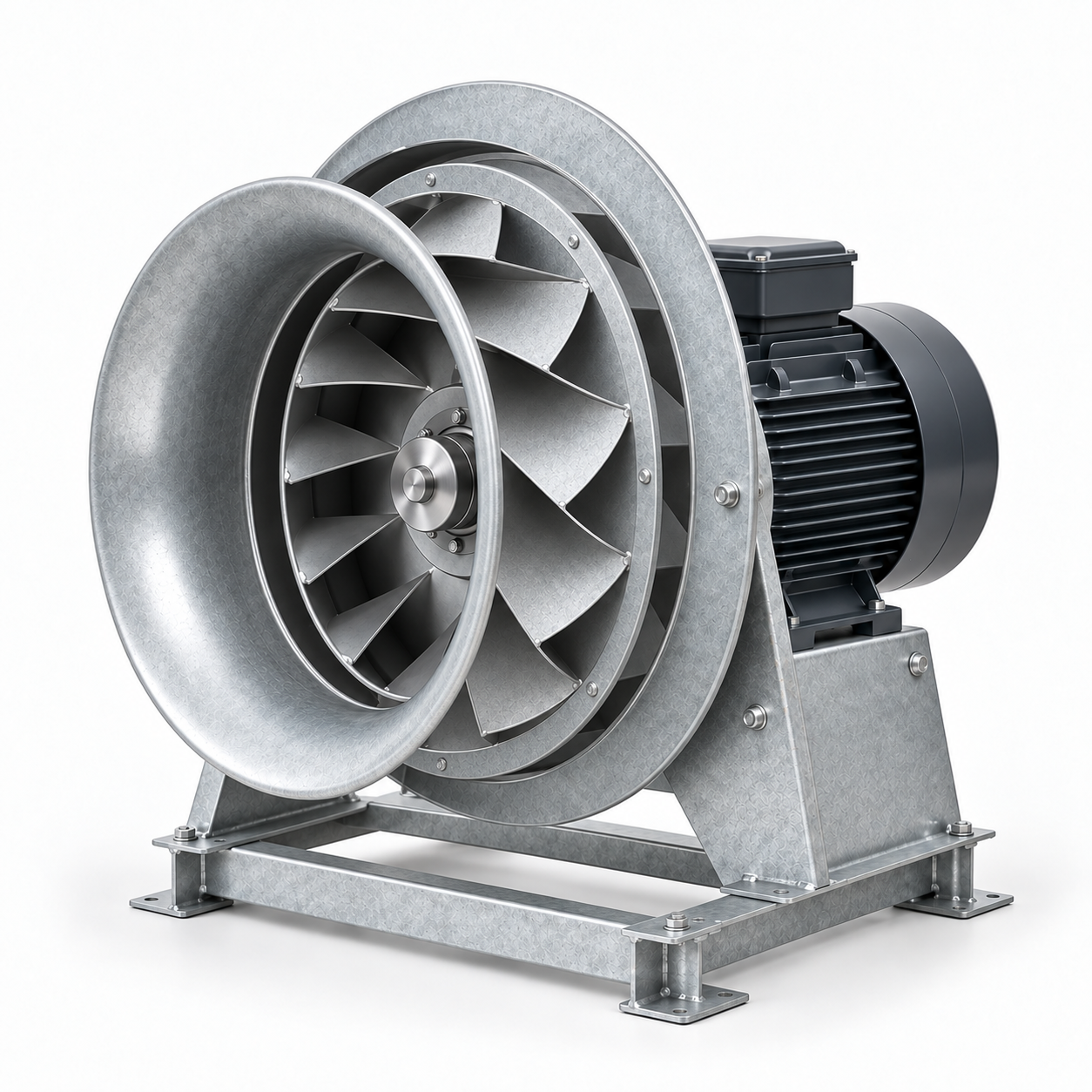
Centrifugal plug fan
A centrifugal fan without a volute casing: the motor drives the impeller, which discharges air into the surrounding unit chamber. The image shows one construction example; other AHU fans have different arrangements.
Supply, extract and supply-and-extract units: how they work, what they contain, and how modular, compact, heat-recovery, hygienic and DX arrangements are selected, installed and maintained.

Closed sectional casing, access doors and connections. An illustrative general view.
Basics and classification
ContentsAn air handling unit (AHU) moves and, where specified, treats air before it enters or leaves a building. Its casing brings the selected fans, filters and treatment sections together. Ducts distribute the air; room terminals deliver or remove it. The unit is one part of the ventilation system.
A standalone fan moves air; a complete AHU combines the functions needed for a particular duty. A fan-coil mainly treats room air and does not, by itself, establish the required outdoor-air supply.
An AHU is assembled from functional sections. Their order follows the treatment task, operating conditions and required service access. The definitions below explain the principal components; the separate portraits show examples of their construction.
Heating and cooling coils change air temperature; a sufficiently cold coil also removes moisture as condensate. Heat recovery transfers energy between air paths. Humidifiers add moisture. Sound attenuators reduce transmitted sound. Drain pans collect water; access sections make inspection, cleaning and replacement possible. No list of components guarantees that a particular unit contains all of them.
A centrifugal fan without a volute casing: the motor drives the impeller, which discharges air into the surrounding unit chamber. The image shows one construction example; other AHU fans have different arrangements.
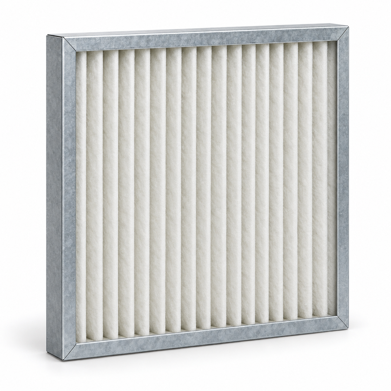
Pleated fibrous media in a rigid frame captures particles from passing air. Select the filtration class and pressure loss from the requirements and the technical documentation for the actual filter.
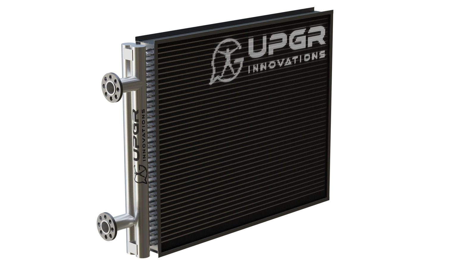
A finned coil transfers heat between its liquid circuit and the passing air. Heating or cooling duty depends on the selected fluid temperatures and operating conditions; the image does not establish capacity.
Outdoor air comes from outside. Supply air is delivered to rooms. Extract air leaves rooms; the part discharged outdoors is exhaust air. Recirculated air is the part returned for further supply. Outdoor-air flow and total supply flow are therefore different quantities in a mixing system.
The example below shows two separate paths. A heat-recovery device couples them thermally; it is not an intentional air-mixing connection. A mixing section is a different function, permitted only where the air quality and project requirements allow recirculation.
Two paths, with separate air streams
Supply path
Extract path
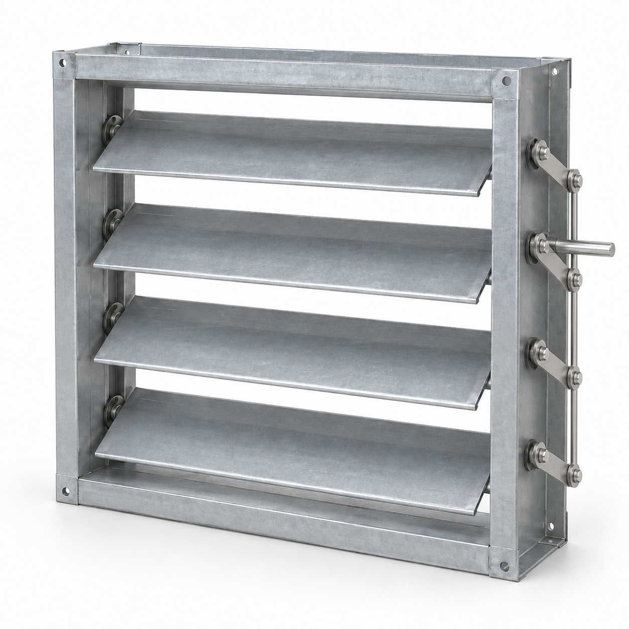
Several movable blades in a rectangular frame change the open air passage when their shafts turn. A linkage couples the blades. The actuator and shutoff or control purpose are specified for the actual construction.
Supply/extract describes air paths. Modular/compact describes construction. Recovery describes energy transfer. Hygienic describes execution. DX describes the cooling or heat-pump circuit. These are intersecting criteria: a modular supply-and-extract unit may also be hygienic and use DX cooling.
For a fair comparison, fix airflow, external pressure, entering air state, required leaving state, filter duty and acoustic limits. Then compare verified performance, electrical input, installed size, service access and lifecycle cost. A larger nominal airflow or one peak efficiency value is not an overall ranking.
| Criterion | Question | Options |
|---|---|---|
| Air function | Where air is moved | Supply · Extract · Supply and extract |
| Construction | How the assembly is packaged | Modular · Compact |
| Energy transfer | Whether extract-air energy is recovered | Heat recovery |
| Hygiene | How cleanliness can be achieved and maintained | Hygienic execution |
| Thermal circuit | How the coil receives or rejects heat | Liquid-to-air coil · Direct expansion (DX) |
| Installation location | Exposure to the environment | Indoor · Outdoor |
| Mounting and support | How the unit loads are supported | Floor/base mounted · Suspended, where permitted |
| Air-path arrangement | How two air paths are positioned | Stacked · Side-by-side |
The control chain runs from measurement to decision and action: sensors provide values, the controller compares them with setpoints and interlocks, and controlled devices change the process. A frequency drive regulates a compatible fan motor; damper actuators change air passages, and liquid control valves regulate flow through a coil. The control cabinet houses equipment and the operator panel provides an interface. Neither is a synonym for the controller.
Specify start/stop sequences, confirmation that the commanded fan is actually running, with airflow proof where required, dirty-filter alarms, frost protection, heater over-temperature protection, condensate alarms and the fire-system interface as applicable. BMS means building management system: a communication connection does not prove that every required point or safety function is included.
Sensors provide measured values to the controller. A measurement signal describes a condition; it does not itself switch a protective circuit.
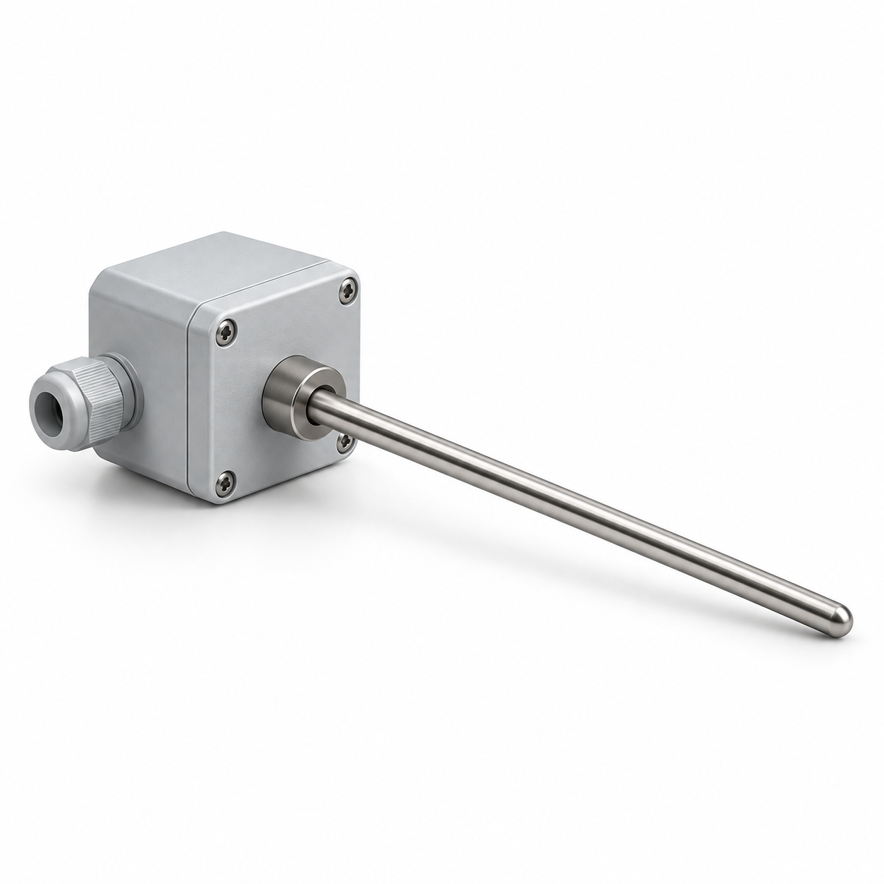
The probe supplies a temperature signal for regulation. Its position must correspond to the air stream and control task being measured.
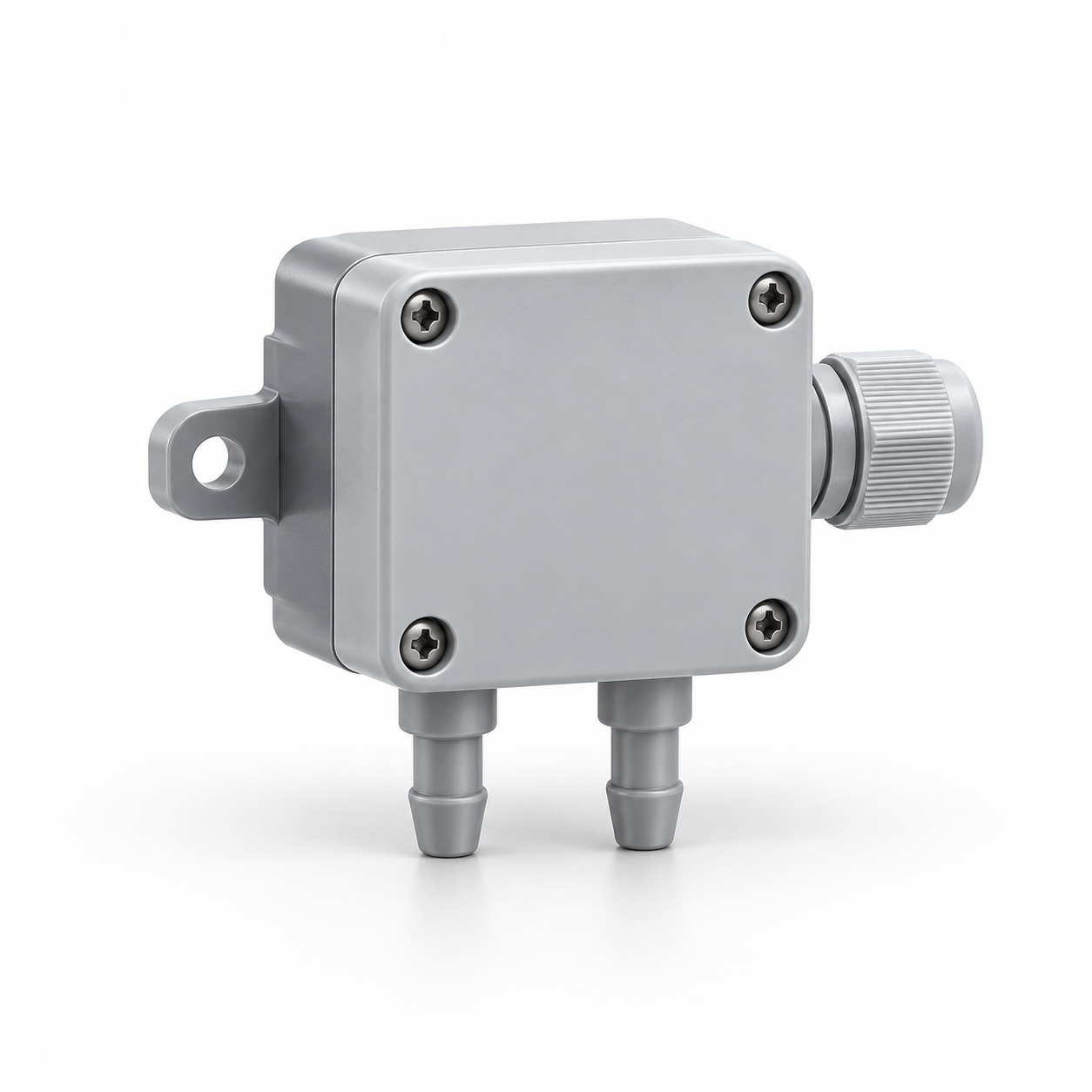
The sensor provides a differential-pressure signal for the selected control scheme. The result depends on the pressure points and measurement range.
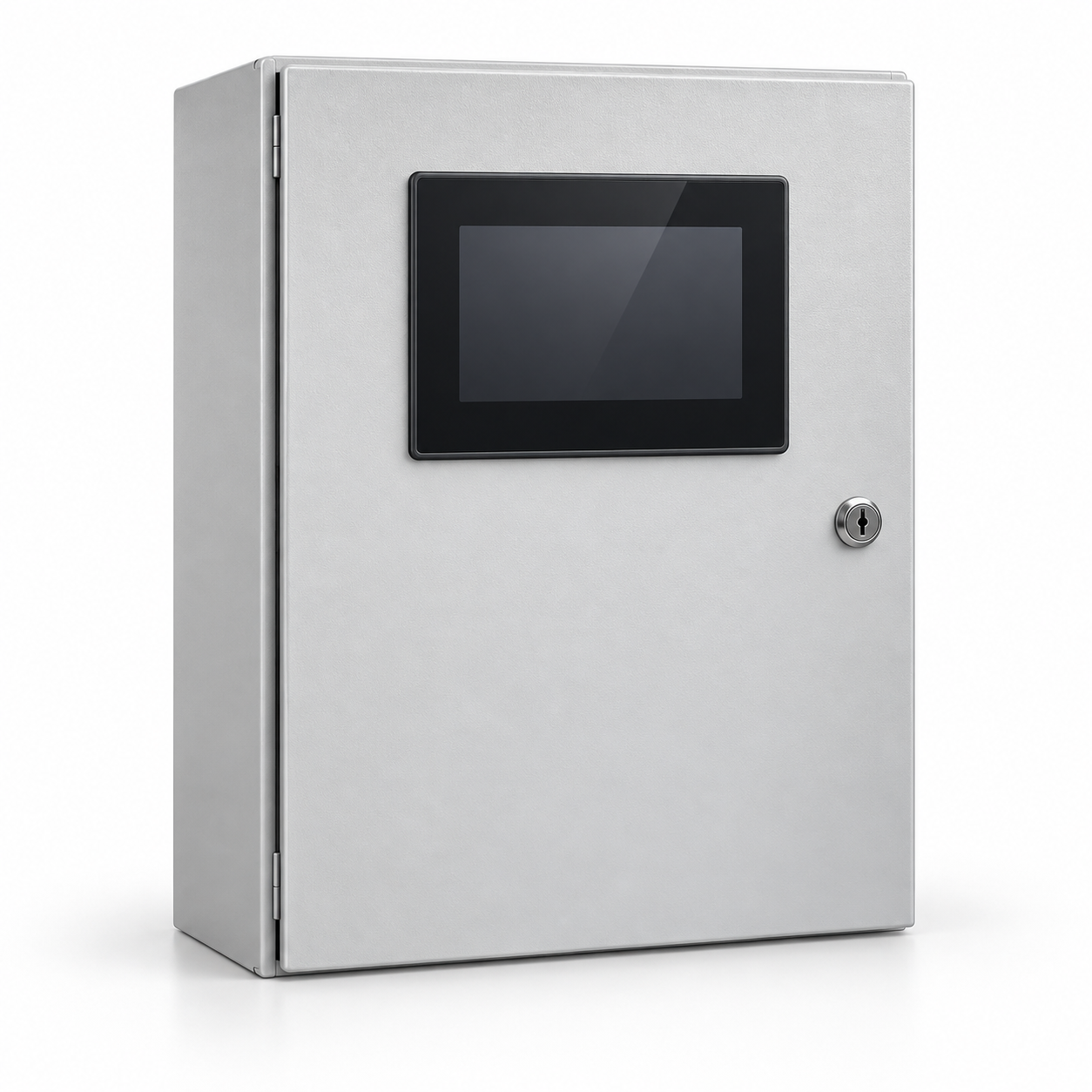
The controller processes the signals and issues commands; the cabinet houses the equipment. A frequency drive applies a speed command to a compatible motor. Valve and damper actuators perform their own control tasks.
The cabinet houses control equipment; the operator panel gives access to operating settings. The control scheme defines the available functions and interfaces.
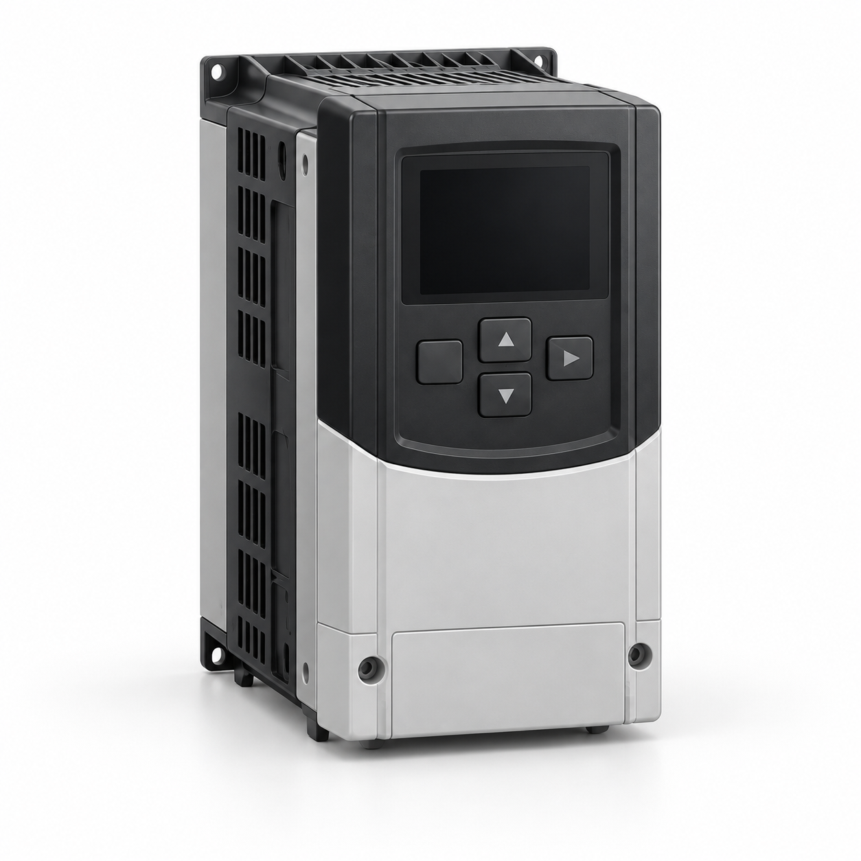
A variable-frequency drive changes the electrical supply frequency to regulate a compatible motor. A speed command alone does not confirm actual airflow.
A relay or thermostat can signal a limit condition to the specified circuit. The local switch is operated for service isolation. These roles and the actual protection sequence are checked separately.
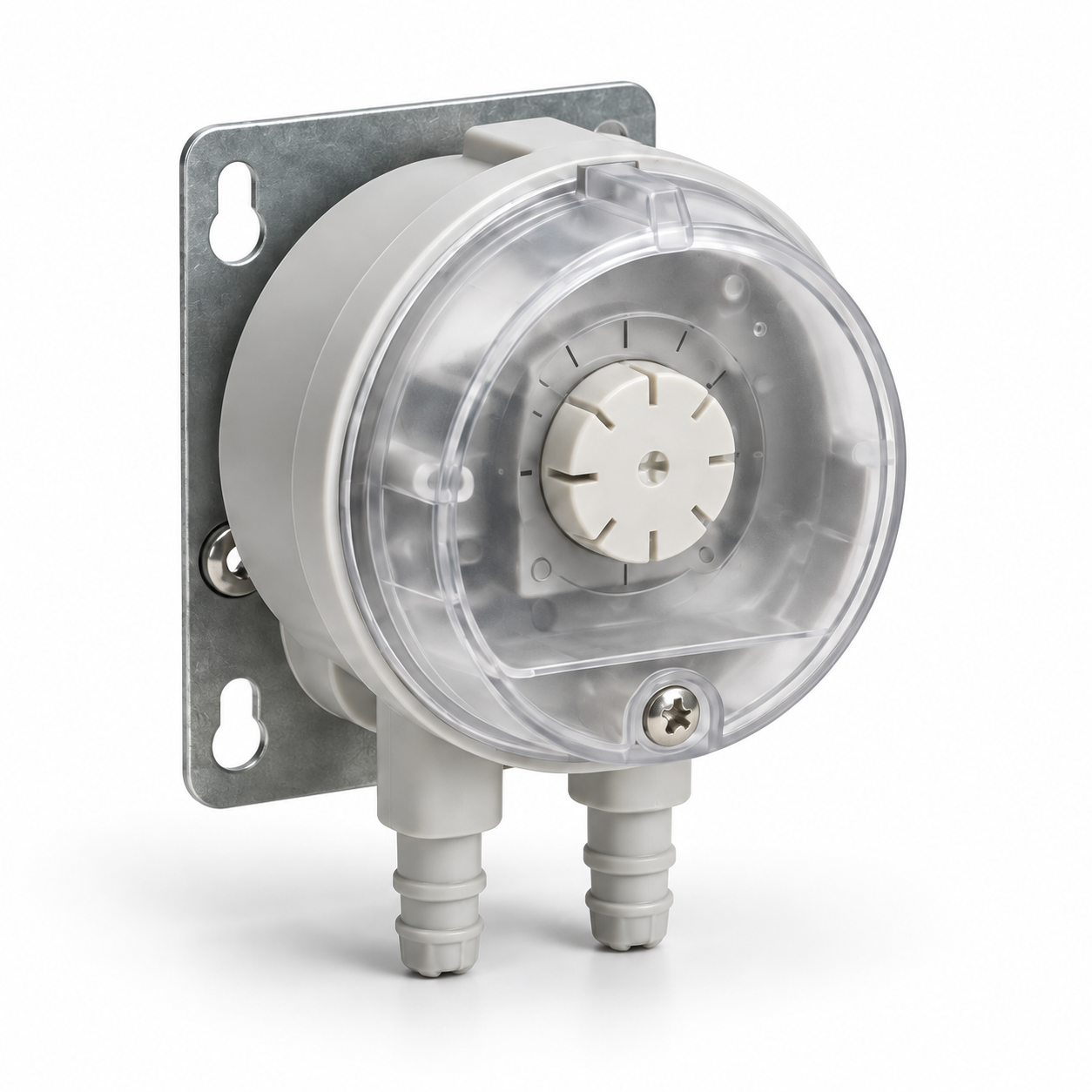
A pressure switch changes its output at a defined pressure difference. Connected to the appropriate pressure points, it can signal increased filter resistance.
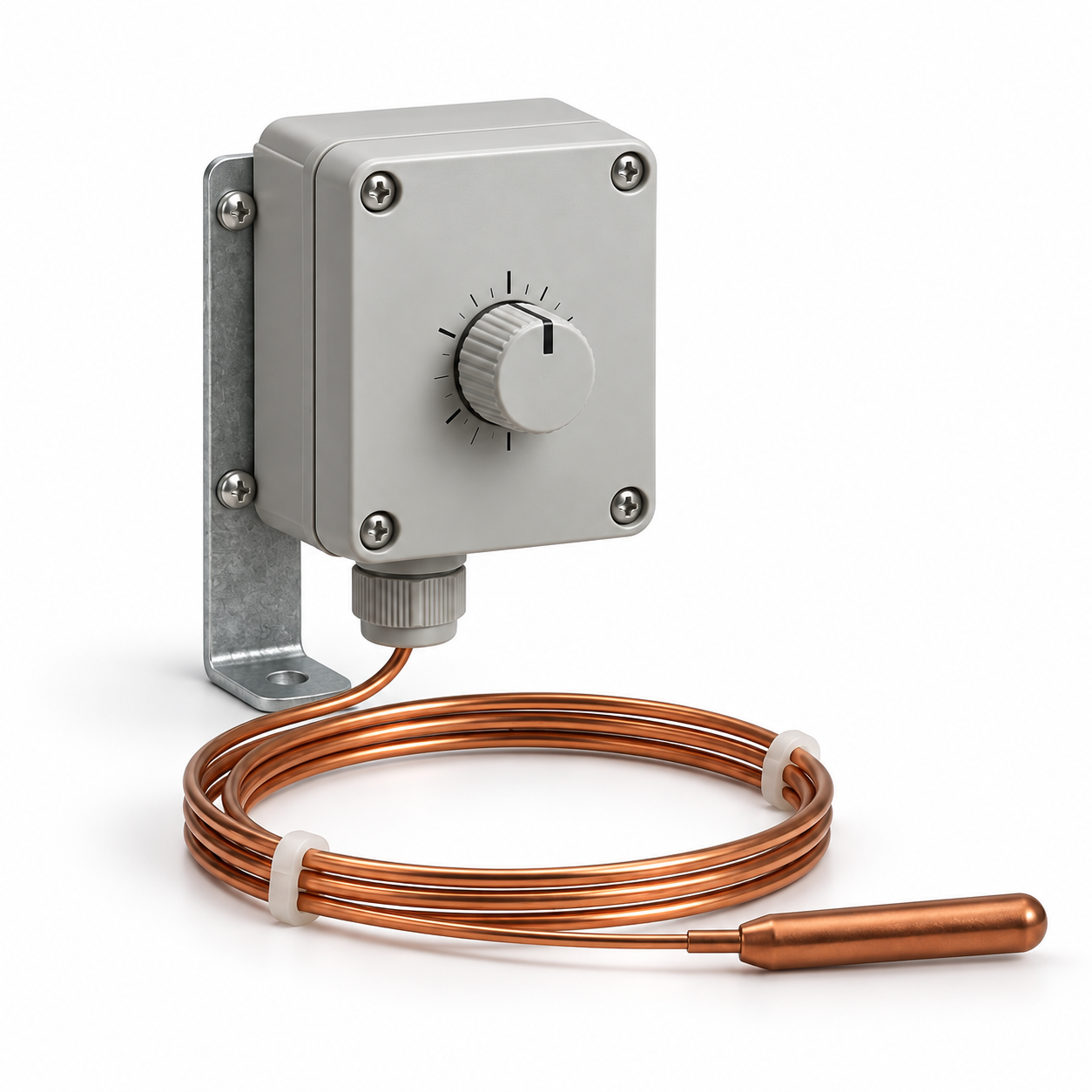
The thermostat responds to temperature at its sensing bulb. Protection across an entire coil requires a sensing arrangement and control sequence with the required coverage.
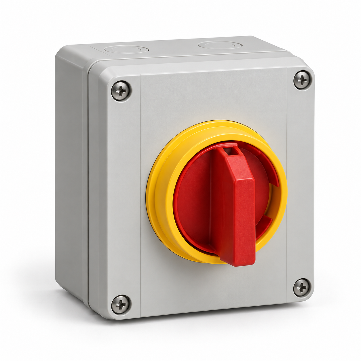
The local switch is used to disconnect power during service under the specified procedure. Its isolating capability and the required verification are determined for the actual installation.
Air paths and functions
ContentsA supply unit draws in outdoor air and delivers it after the specified filtration and treatment. The building still needs an extract or relief path. Adding supply air without checking the return path can change room pressure and prevent the intended airflow.
Distinguish a unit handling only outdoor air from one mixing outdoor and recirculated air. The outdoor-air requirement, winter heating duty and frost protection must be checked for the actual intake conditions.
An extract unit removes air from rooms or processes. Replacement air must enter through a designed supply or transfer path. Filters, materials and fan execution depend on the extracted contaminants and temperature.
Ordinary general-ventilation equipment is not automatically suitable for grease, corrosive fumes, explosive atmospheres or smoke extraction. Those duties require a separately specified system and evidence for the exact application.
A supply-and-extract unit combines two air paths in one coordinated assembly. The flows are selected to meet ventilation and room-pressure requirements; equal nominal flows do not by themselves establish a balanced building.
The assembly may include heat recovery, but having two fans does not prove that it does. Check air-path separation, intake and discharge positions, leakage, control interaction and access to both sides.
Construction and placement
ContentsModular AHUs combine functional sections to suit a duty and layout. This allows the air treatment, casing cross-section and access arrangement to be selected together. Modules may be delivered separately or joined before delivery.
A functional section is not necessarily a transport block. Confirm the shipping splits, lifting points, site joints, overall dimensions and clear withdrawal space for the largest replaceable component.
A compact unit puts a defined combination of functions into a relatively small enclosure. It can be supply-only, extract-only or two-stream with recovery. A box fan is one possible assembly; it is not the definition of every compact AHU.
Compare the complete installed envelope, including ducts, drainage and filter access. A smaller casing may increase internal air velocity, pressure loss and sound; suitability depends on the measured selection data.
Location is a separate classification from function. Indoor units need a suitable plant room and drainage. Outdoor units need weather-resistant construction, protected openings, a suitable base and freeze protection. Roof placement also requires structural and access coordination.
Placement has three independent attributes: location indoors or outdoors; mounting on a floor/base or by a permitted suspended arrangement; and, for two air paths, stacked or side-by-side construction. A location does not determine the mounting or air-path arrangement. Confirm the permitted orientation, load-bearing supports, drain position, weather protection and access for the actual assembly.
Door hardware provides a grip, retains the service panel and helps maintain access to the casing. A pull handle, a latch or clamp and a hinge perform different tasks; their compatibility depends on the actual door construction.
Check the panel thickness, mounting pattern, opening direction, gasket contact, service clearance and materials for the operating environment. Loads, sealing and any safety function require confirmation for the complete assembly.
A fixed grip used to move a service door or removable panel. It is not itself a latch and does not establish door sealing.
Drag with a mouse to rotate. On touch screens, swipe horizontally to rotate or vertically to scroll the page. Use + and − to zoom. With the model focused: 1 = front, 2 = side, 0 = perspective view; Escape closes the model.
Inspect the grip and its mounting feet from different sides. This is a fixed pull handle; the clamping action is shown in the separate door-clamp model.
A clamp that turns to engage or release a panel. In the illustrated screw-and-spring arrangement, turning the screw changes axial position; the spring changes length along the same axis.
Drag with a mouse to rotate. On touch screens, swipe horizontally to rotate or vertically to scroll the page. Use + and − to zoom. With the model focused: 1 = front, 2 = side, 0 = perspective view; Escape closes the model.
Turn the clamp to inspect its retaining nose. The second control rotates and moves the screw along its axis while the spring changes length. Rotation and screw adjustment are shown separately; this model does not include a service door. Small fastener details are simplified.
These are separate construction examples. The 3D motion explains the mechanism; it does not establish loads, tightening torque, permitted travel or compatibility with a particular unit.
Air treatment and hygiene
ContentsHeat recovery uses a temperature or moisture difference between extracted and incoming air to reduce treatment demand. A plate device exchanges energy across separating surfaces; a rotor transfers it through a rotating matrix; a run-around system uses two coils and a pumped liquid loop. Moisture transfer depends on the selected technology.
Compare performance at the same airflows and conditions, plus leakage or carry-over (extract air retained in the rotor and transported into the supply path), pressure losses, pump/fan energy, bypass and frost strategy. A high recovery percentage is not the same as annual energy savings or adequate supply temperature.
Hygienic execution addresses cleanability, drainage, access, suitable internal surfaces, sealed filter mounting and controlled leakage. It is a construction and verification requirement that can apply to different airflow and treatment arrangements.
Define the room risk, pressure relationships, filtration stages and cleaning procedure. Fine-particle or high-efficiency filtration does not make a complete installation suitable for a cleanroom or clinical process by itself. The project needs the required performance evidence and commissioning results.
DX means direct expansion: refrigerant evaporates in the air-cooling coil and absorbs heat. In a reversible heat-pump system, a coil can also heat air when refrigerant condenses in it. A water coil instead receives cooled or heated liquid from a separate plant.
A DX AHU must be matched to its refrigeration equipment and controls. Check refrigerant, airflow range, coil circuits, capacity modulation, outdoor limits, defrost interaction and permitted pipe lengths/elevations. Nominal cooling capacity alone does not establish compatibility.
Hot water, glycol mixtures, refrigerant, electricity or steam may provide treatment energy where the selected section supports them. Specify fluid type, concentration, temperatures and flow separately from coil materials. Glycol changes heat transfer and pressure loss as well as freeze resistance.
Relative humidity expresses how close air is to saturation at its current temperature; moisture content expresses how much water vapour it carries. Heating alone lowers relative humidity without removing water. Cooling below the dew point (the temperature at which water vapour begins to condense for the stated moisture content and pressure) removes water as condensate. Particle filters do not remove every gas or odour; specify the contaminant and the corresponding treatment.
Application and selection
ContentsOffices, schools, retail and accommodation need ventilation matched to occupancy and operating hours. Production spaces add process emissions and heat loads. Pools add high moisture and corrosive conditions. Laboratories, healthcare and clean areas add pressure, contamination and verification requirements.
A shared AHU name does not make these duties interchangeable. Establish whether air may be recirculated, whether energy recovery creates a contamination concern and which areas need separate systems. Fire, explosion, process exhaust and critical hygiene requirements need project-specific design.
Begin with room use, occupancy, pollutant and moisture sources, design weather and the required indoor conditions. Determine outdoor-air needs, supply/extract balance, pressure relationships and operating modes before choosing a casing size.
Coordinate duct resistance, sound paths, water or refrigerant services, electric power, drainage, structure, fire strategy and control responsibilities. The result is a system specification and a defined AHU duty; a catalogue selection is only one part of that design.
Specify supply, outdoor and extract airflows in m³/h or m³/s, the design air conditions and the required external static pressure in Pa at those flows. State the inlet/outlet connection boundaries for each air path.
Account separately for losses in internal filters, coils and other sections. Check the fan duty point against both the network and internal components, with the stated filter condition. The selection sheet must connect this duty to the chosen configuration, performance and limits.
Collect these inputs in one dated brief. Use the same duty and revision when reviewing the selection, comparing the supply scope and planning acceptance.
Estimate the sensible load of a stated air stream; a full AHU selection still requires the project duty and verified component performance.
Calculate sensible air loadCalculate the heat rate associated with a specified temperature change in one air stream. Enter all five values for your stated operating conditions.
Mass flow ṁ = ρ × V̇ / 3600; temperature change ΔT = Tout − Tin; sensible heat rate Q̇ = ṁ × cp × ΔT. With the units below, the result is in kW. Positive Q̇ means heating; negative Q̇ means cooling. Zero flow or zero temperature difference gives zero sensible load.
For a steady, single-phase air stream with constant user-supplied properties. The balance excludes latent heat, moisture changes, phase change, shaft work and kinetic/potential energy changes. It does not select a fan, coil or complete AHU.
Interactive calculation requires JavaScript. The formula, units, scope and reference information remain available here for manual use.
This browser cannot retain the local inputs. They remain available until this page is left.
For a steady, single-phase air stream with constant user-supplied properties. The balance excludes latent heat, moisture changes, phase change, shaft work and kinetic/potential energy changes. It does not select a fan, coil or complete AHU.
The draft contains the topic, entered parameters, method, result, assumptions and unanswered questions. It remains in this page and is not sent.
Choose a topic explicitly to prepare a local draft.
Airflow is volume per time: divide m³/h by 3600 to obtain m³/s. For an illustrative sensible-air heat balance, Q = ρ × cp × V × ΔT: Q is heat rate in kW; ρ is air density in kg/m³; cp is specific heat in kJ/(kg·K); V is flow in m³/s; ΔT is temperature change in K. Use density for the stated air condition.
This balance excludes condensation, humidification, leakage and detailed coil performance. Moisture processes require an enthalpy and water balance; enthalpy is the heat-content measure used for moist air. Final selection also needs pressure losses, fan curves, sound, part-load and frost checks. The shared tool calculates only the constant-property sensible air balance; it does not provide equipment sizing or a project design output.
From manufacture to service
ContentsA selected AHU becomes a manufactured configuration through a confirmed section schedule, casing and material specification, fan/coil/filter selections, controls scope and drawings. Production may use standard modules while the assembled duty remains project-specific.
Agree factory checks, transport splits, identification and supplied accessories before release to manufacture. An educational description of production is not evidence that a supplier manufactures a proposed configuration or includes every accessory.
Check the delivery route, lifting plan, support loads and level base against the selected assembly. Keep service clearances and coil/filter withdrawal paths open. Join transport sections, seal joints and support connected ducts and pipework as instructed for that unit.
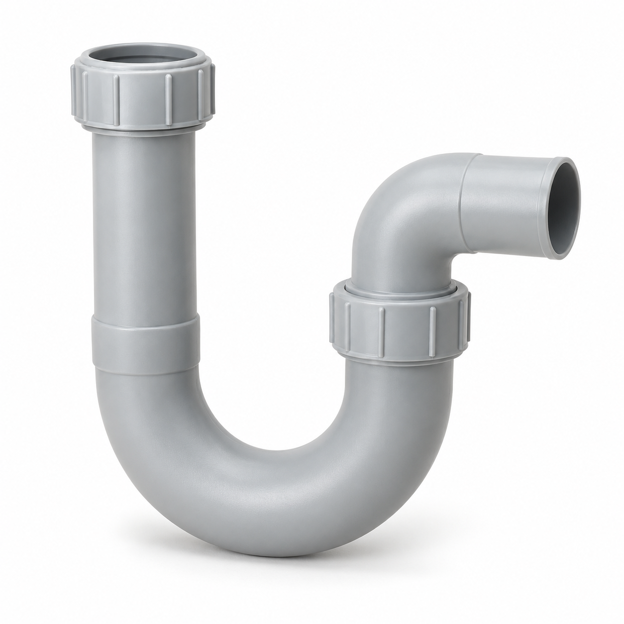
A condensate trap maintains a seal between the air path under pressure and the drain while allowing water to leave the pan. Connect the drain with the required slope and a trap suited to the sign and magnitude of pressure at the connection; a universal trap depth is insufficient. Confirm electrical isolation, protective electrical bonding of accessible conductive parts to the protective conductor, as specified in the wiring design, frost measures and weather protection. Installation details follow the approved drawings and unit instructions.
The low bend of this condensate trap retains water after filling and forms a water seal between the air path and the drain. The required trap geometry and water-seal depth depend on the sign and magnitude of pressure at the connection; they are selected for the installation.
Operate against the commissioned airflow, temperature and schedule settings. Track fan power, drain performance, repeated alarms and the pressure difference across filters at the stated airflow. For a filter, the measured difference is used to assess flow resistance. A changed reading can also reflect changed airflow, so it does not prove fouling on its own.
Optimise schedules and demand control while preserving required ventilation and room-pressure relationships. Compare total fan, pump, heating and cooling energy across seasons. A reduced fan speed saves no useful energy if it leaves the occupied space under-ventilated.
Use the unit instructions and actual operating conditions to set intervals. Inspect and replace filters at the stated limit; inspect coils, fans, belts where fitted, seals, drains, recovery devices and sensors. Record contamination, damage and the work performed.
Isolate energy before opening service areas and follow the required hygiene procedure. Clean with methods compatible with the materials and coatings, then restore seals, guards and settings. Filter condition cannot be judged from elapsed time alone.
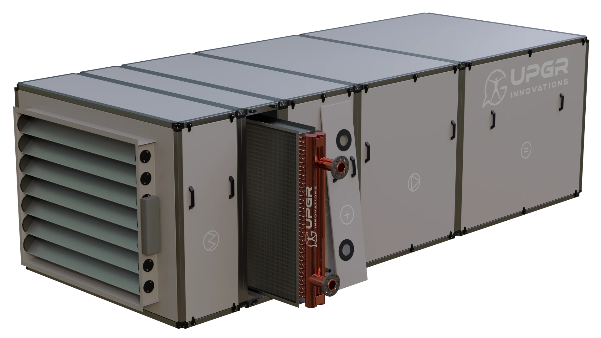
Access to a finned coil in a sectional AHU. Reserve space for removing the access panel and handling the coil; the actual removal procedure follows the equipment documentation.
Record when the fault occurs and compare it with commissioning data; one symptom may have several causes.
Related explanations
Related explanations
Related explanations
Related explanations
Confirm the failed component and cause before ordering work. A leaking coil, failed motor, damaged seal and control fault require different repairs. Address the cause, including freezing, corrosion, electrical faults or incorrect operating conditions.
Use compatible parts and the manufacturer’s approved repair method. Refrigerant work and safety functions need qualified personnel and the required checks. After repair, verify leakage, protection, airflow and the affected treatment duty; document the change and warranty implications.
Replacement starts from the current duty and interfaces, not the old model name alone. Survey dimensions, access, connections, service side, fan pressure, coil conditions, electrical supply and controls. Confirm whether the original building duty has changed.
Check component withdrawal and whole-unit transport separately. A replacement fan, filter or coil can alter resistance, energy use and controls. Re-select and recommission the affected system; an equal envelope does not prove equal performance.
Documents and procurement
ContentsAlso establish electrical/control diagrams, conformity or test evidence required for the project, commissioning records, spare-parts references and the final supply list. Each issued document must match the unit, configuration and revision. A general example or family brochure is not that unit’s issued passport or approval.
Obtain the applicable written warranty for the exact supplier and configuration: start event, duration, covered parts/work, exclusions, required commissioning and maintenance records, and the fault-report procedure. These terms differ by contract.
Record serial identification, operating conditions, alarms, photographs and service history when reporting a fault. Do not infer coverage from a catalogue page, a generic warranty period or an unapproved repair. No warranty term is offered by this reference guide.
Compare quotations against the same duty and revision. Confirm responsibilities at every interface.
Ask for a complete configuration code, exclusions, price/currency and validity, delivery basis, production lead time, packing and acceptance documents. Reference coverage is not stock, an offer or a service commitment. Use the manufacturer catalogue to review actual families, then obtain a project-specific selection and commercial offer.
A guide to equipment and selection; the final configuration and performance require project-specific confirmation.