Equipment reference
Centrifugal pumps
An impeller transfers energy to a continuous liquid flow. Understand the hydraulic parts, operating range and suction conditions before choosing a configuration.
Energy transfer
Liquid enters the rotating impeller and gains energy. The casing or diffuser guides the discharge and converts part of its velocity energy into pressure. In the wider rotodynamic family, mixed-flow and axial pumps use different flow directions.
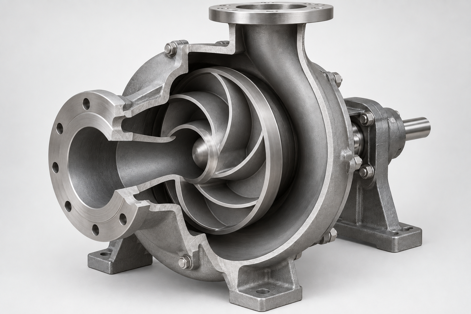
Centrifugal pumps and in-line construction
The casing contains the liquid; the impeller moves it; the shaft transmits torque. Bearings support the rotor. A shaft seal limits leakage where a rotating shaft crosses the casing. Coupled, close-coupled and glandless constructions solve these functions differently.
An in-line connection layout can use a centrifugal impeller. It describes the nozzle arrangement; the energy-transfer principle remains centrifugal. Separate motor wetting and shaft orientation from both of these attributes.
Operating range
The duty point must be checked on the exact speed and impeller-diameter curve. Also compare efficiency, absorbed power, minimum flow and the permitted operating region. The best-efficiency point is a reference for selection, not permission to ignore changing system demand.
A single-stage and a multistage centrifugal pump are compared at the required flow and head. Successive stages can raise the head at the same through-flow; they do not automatically improve every duty or multiply its flow.
Suction and cavitation
Check the available suction head above vapour pressure at the hottest fluid and lowest inlet level. Allow the required margin over the pump requirement. Noise alone does not establish cavitation: air entry, mechanical faults and pipe vibration can produce similar symptoms.