Equipment reference
Pumps
A pump supplies mechanical energy to a liquid so that it can circulate, rise to another level or move against pressure and friction. The working mechanism, liquid and system duty determine which construction is suitable.
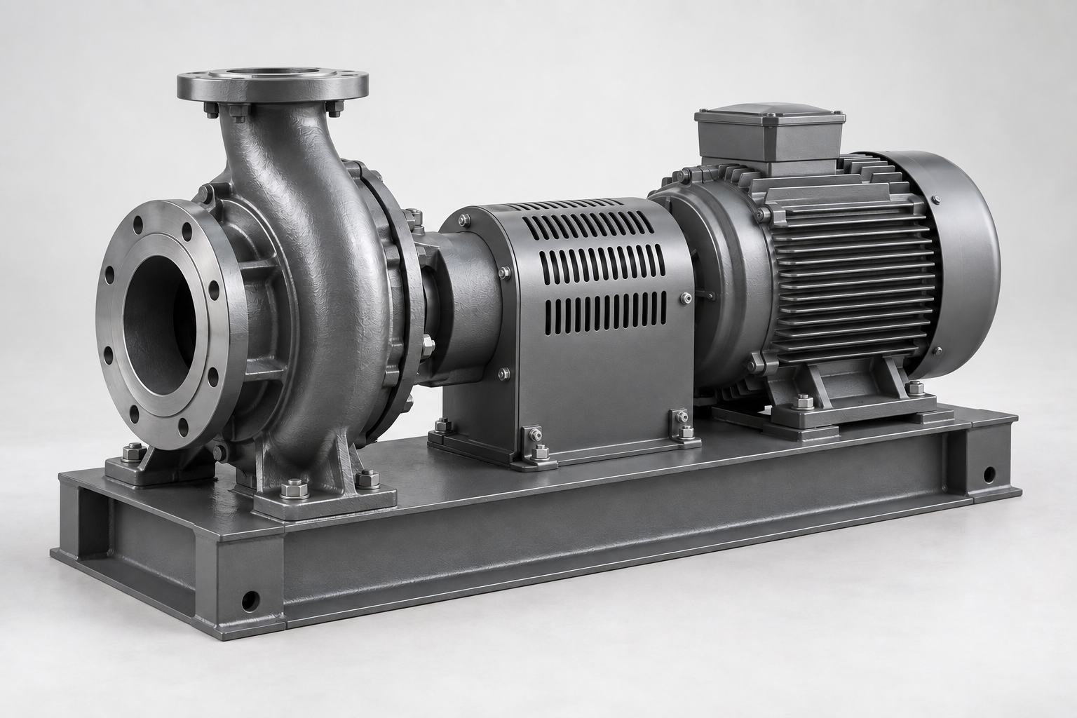
Principles and duty
What a pump does
A pump supplies mechanical energy to a liquid so that it can circulate, rise to another level or move against pressure and friction. Rotating impellers and enclosed displacement volumes are different ways to perform that task. The system determines the actual duty.
Flow, head and power
Flow Q is the volume moved per unit time. Head H is energy per unit weight of liquid, expressed in metres. It is not the same as discharge pressure: pressure conversion depends on density, inlet pressure, velocity and elevation. Motor rated power does not equal useful hydraulic power.
Hydraulic power is the power transferred to the liquid; shaft power is the mechanical input to the pump; electrical input also includes motor and drive losses. Efficiency is useful output divided by the corresponding input. Always name the boundary when comparing power or efficiency.
Absolute pressure is measured from vacuum; gauge pressure is measured relative to local atmospheric pressure. Differential pressure is the difference between two measurement points. Use absolute pressure for vapour-pressure and suction checks; a gauge reading alone is not that quantity.
| Quantity | Meaning and common units |
|---|---|
| Flow Q | Volume per time: m³/h, l/s. |
| Head H | Added energy per unit weight: m. |
| Pressure p | Force per area: Pa, kPa, bar. State absolute or gauge. |
| Power P | Energy per time: W, kW. Distinguish hydraulic, shaft and electrical power. |
| Efficiency η | Useful output divided by input; specify pump or complete set. |
Pump and system operating point
For a centrifugal pump, the steady operating point is the intersection of the pump curve and the system curve at the chosen speed. Changing a valve, pipe resistance, liquid level or speed changes this point. Maximum flow and maximum head are generally different points, not one combined rating.
- Pump curve
- System curve
- A Operating point
How a centrifugal pump works
Centrifugal pumps use a radial-flow impeller. The wider rotodynamic family also includes mixed-flow and axial-flow designs. Compare exact curves, efficiency, permissible duty and suction conditions for the configuration.
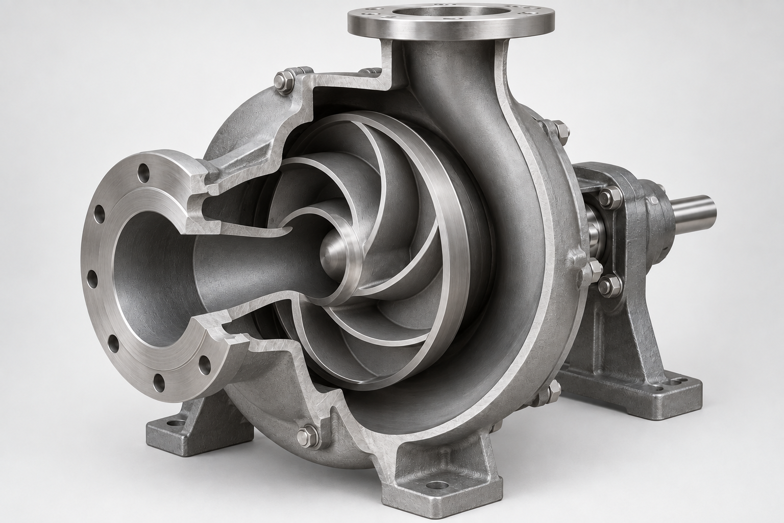
Liquid enters near the centre of the impeller, gains energy in rotating channels and leaves toward the casing. The volute or diffuser collects the flow and converts part of its velocity energy into pressure. The shaft brings mechanical power from the drive.
Positive-displacement
A changing enclosed volume moves the liquid. Rotary and reciprocating mechanisms include gears, screws, pistons and diaphragms. Pressure protection and fluid compatibility are essential; an unrestricted centrifugal-pump selection rule cannot simply be transferred to these pumps.
Construction and installation form
Components and their functions
The pump transfers energy through a working element and contains the liquid in a pressure-bearing body. The arrangement differs between families; understand each component’s job before comparing a product drawing.
Working element
An impeller transfers energy continuously through rotating passages. Gears, screws, pistons or a diaphragm in a positive-displacement pump instead move enclosed volumes. These mechanisms have different flow, pressure and fluid limits.
Casing and connections
The casing contains liquid and connects the inlet to the outlet. In a centrifugal pump, a volute or diffuser collects flow leaving the impeller and converts part of its velocity energy into pressure. Flanges and connections must suit pipe loads and pressure.
Shaft and bearings
The shaft transmits torque from the drive. Bearings support the rotating assembly and carry radial and axial loads; their lubrication and allowable loads depend on the design. Shaft alignment matters for sets with a separate coupled motor.
Sealing
Static seals close stationary joints. A shaft seal limits leakage where a rotating shaft crosses the casing; a mechanical seal uses mating faces. A wet-rotor design separates the electrical stator from the wetted rotor by a barrier, so its sealing arrangement differs.
Drive and control
The drive supplies mechanical power. A speed controller changes rotational speed to suit demand within the permitted range. Sensors and protections supervise pressure, level, temperature or electrical conditions; their presence and settings depend on the application.
Base and supports
Supports carry the set and maintain alignment. Pipe supports carry the pipework independently where required; excessive nozzle loads can distort the casing or disturb alignment. Service space is part of the installation requirement.
Rotor, shaft and suction arrangement
In an electric motor, the rotor is the rotating part and the stator is the stationary electromagnetic part. The wet/dry distinction below describes whether pumped liquid contacts the rotor, not whether the complete pump is submerged.
Wet rotor means the rotor is wetted by pumped liquid; dry rotor means it is outside that liquid. This says nothing about whether the shaft is horizontal or vertical. Those words describe the shaft’s spatial orientation, not the flow direction or inlet/outlet alignment.
Single-suction and double-suction describe entry to the impeller from one or both sides. Double suction does not mean two separate pumps. Single-stage and multistage describe the number of successive energy-adding stages. Record these axes independently when specifying a configuration.
| Independent attribute | Examples | What it tells you |
|---|---|---|
| Rotor wetting | Wet / dry | Motor and sealing construction |
| Shaft position | Horizontal / vertical | Orientation, access and support |
| Connections | In-line / end-suction | External pipe arrangement |
| Stages | Single / multiple | Successive energy-adding stages |
| Impeller entry | Single / double suction | Entry from one or both sides; independent of stage count |
In-line
Inlet and outlet connections lie on one pipe axis. This is a connection arrangement, not a statement about motor wetting or performance. Check mounting support, permitted orientation and the space required for maintenance.
Multistage
Several impellers work consecutively on the same flow to build head. Single-stage and multistage pumps can have different mounting arrangements. Higher final pressure does not remove the need to verify the first-stage suction conditions.
Submersible
The hydraulic assembly, or the complete set including the motor, works in the liquid. Select for the actual fluid, depth, minimum level and cooling mode. Submerged installation does not automatically mean sewage capability.
Applications
Circulation
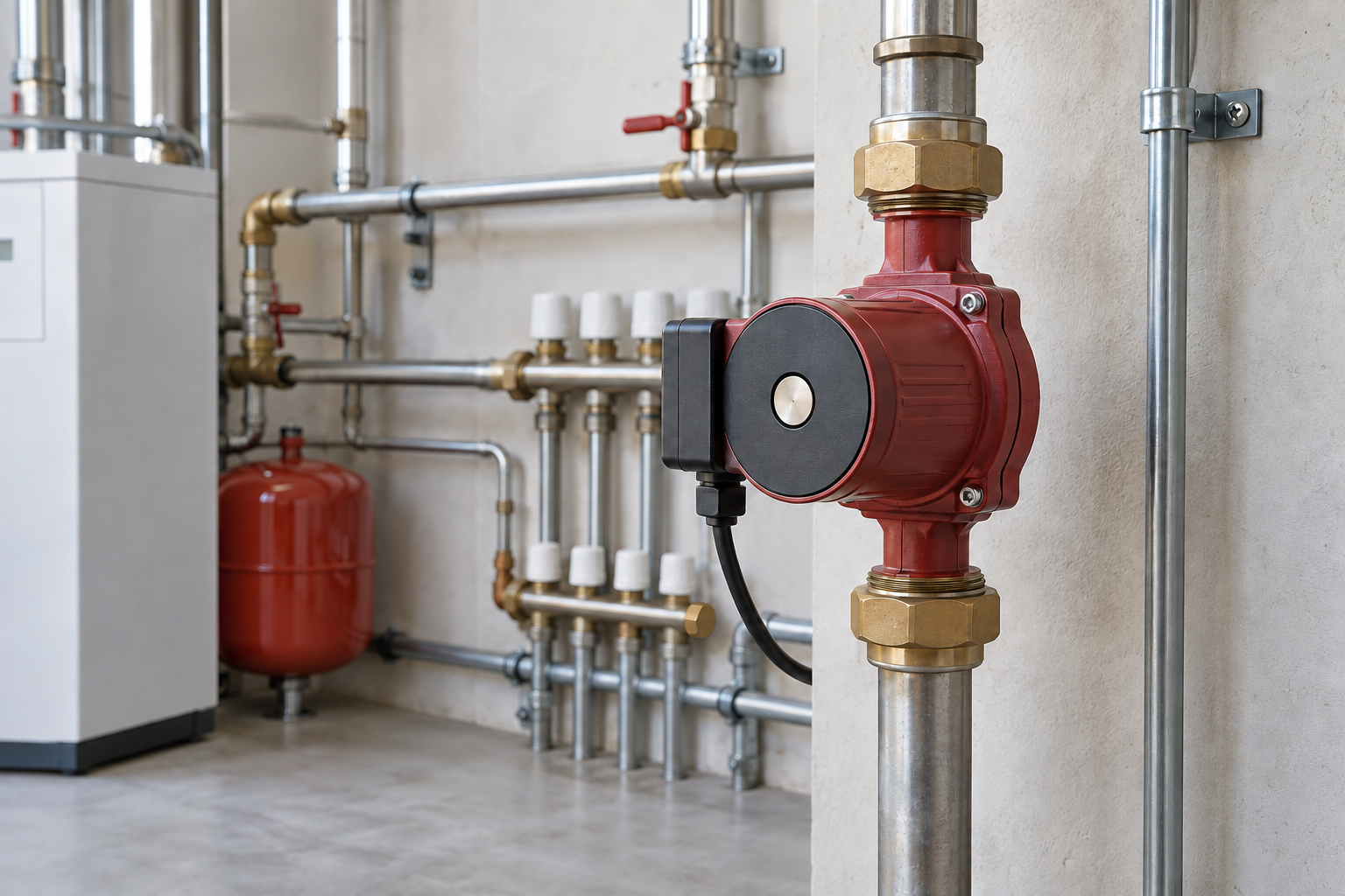
This duty keeps liquid moving around a circuit, such as heating or cooling. The required flow follows the thermal duty and temperature difference; head follows circuit resistance. Wet or dry rotor, speed control and material compatibility are separate choices.
Wastewater and drainage
Identify solids, fibres, abrasiveness and liquid variation before selecting a passage or cutting arrangement. Clean drainage water and sewage impose different requirements. Match both the liquid-handling capability and the station operating range.
Water supply and process duties
Other duties include pressure boosting, wells, irrigation, boiler feed, fire protection, dosing and process transfer. Each adds its own requirements for materials, control, reliability and documentation. An application label alone is neither a verified selection nor evidence of required approval.
Water supply and pressure boosting
Select for the range of demand and pressure at the delivery point. Check inlet pressure, storage or network conditions, control stability and potable-water suitability when applicable.
Wells and boreholes
The dynamic water level is the level during pumping. Together with drawdown, delivery elevation, pipe loss and well yield, it determines the duty; diameter, sand content and motor cooling constrain the installation.
Irrigation
Flow follows the active zones and delivery devices; pressure must remain suitable at the distant outlet. Seasonal levels, filtration, suspended solids and switching between zones change the duty.
Boiler feed
Feed duty combines delivery pressure with potentially hot water and limited suction margin. Verify temperature, pressure, minimum flow, materials and the installation’s available NPSH together.
Fire protection
This duty requires the project’s specified performance, reliability, control and applicable approval evidence. Ordinary water-pump similarity does not establish suitability for a fire-protection system.
Dosing
The task is controlled delivery of an amount over time, often with changing back pressure. Check accuracy over the requested range, pulsation, pressure protection and chemical compatibility; positive-displacement mechanisms are common candidates.
Process transfer
Process liquids may add viscosity, corrosion, abrasiveness, gas or cleanliness constraints. Define normal and abnormal conditions before choosing the hydraulic mechanism, materials, sealing and control.
Liquids and materials
Pumped liquids
Specify composition and concentration, temperature, viscosity, density, solids, gas content and any hygiene requirements. Viscosity is resistance to flow deformation; it affects losses and may change usable pump curves. Density connects head to pressure and hydraulic power. Gas and vapour can disrupt liquid pumping.
Materials and seal compatibility
Casing, impeller, shaft and seal materials may differ. Check each wetted material against composition, concentration, temperature, abrasion and cleaning agents. Stainless steel is a family of alloys; a name alone does not establish corrosion resistance. Seal elastomers and mating faces require their own compatibility check.
Operating conditions and control
Suction conditions and cavitation
NPSH is the suction head above the liquid vapour-pressure level. Available NPSH belongs to the installation; required NPSH belongs to the pump and operating point. Use the specified margin. Cavitation is the formation and collapse of vapour cavities and can reduce performance or damage surfaces.
NPSHA (available) is the installation’s absolute suction total head above the liquid’s vapour-pressure head. NPSHR (required) is a pump requirement at a stated flow, speed and test criterion. NPSH3 specifically uses a 3% head-drop test criterion; it is not a promise of zero cavitation. Do not confuse these quantities or apply a universal margin.
Parallel, series and standby
In parallel, flows are added at equal head to form the combined curve. In series, heads are added at equal flow. The system curve still determines the duty. A standby pump improves availability according to the control scheme; it does not add operating capacity while stopped.
Control and changing demand
Throttling changes system resistance; speed control changes the pump curve. Neither approach removes the need to check minimum flow, stable operating range, motor cooling and suction conditions. For multiple pumps, define start/stop thresholds, alternation, check-valve behaviour and failure response.
Selection and lifecycle
Selection and calculation
Define the full duty range, fluid, suction conditions and installation; then check a documented configuration and its curves. A nominal diameter or motor power alone cannot select the pump. Keep assumptions and missing inputs visible in the selection brief.
Installation
Plan supports, pipe loads, filling and venting points, electric supply, protection and service access. Use the permitted orientation and equipment-specific connection requirements. A dimensionally fitting replacement may still require different supports or controls.
Commissioning and acceptance
Before start-up, verify filling, venting, rotation where applicable, electrical protection and permitted valve positions. Follow the exact equipment procedure. Record flow/head or agreed measurements, electrical load, noise, vibration and control/alarm tests as the operating baseline.
Operation and scheduled service
Compare operating condition with the commissioning baseline and manufacturer limits. Set inspection and maintenance intervals for the actual duty, liquid and environment; no universal interval fits every pump. Track leaks, temperature, vibration, electrical load and control events.
Fault finding
Low flow, noise, leakage and overheating are symptoms, not diagnoses. Compare pressure/flow, valve position, level, rotation, current and vibration with the baseline; distinguish changed system resistance, air entry, cavitation, blockage, wear and drive faults. Isolate energy and pressure before intrusive inspection.
Repair and replacement
Identify the exact execution and revision before ordering seals, impellers, bearings or motors. Material and dimensional similarity alone is insufficient. After repair, check assembly, alignment where applicable, leak tightness and the operating point; reassess selection if the system duty changed.
Documents and supply
Technical documents
Connect the exact designation, execution and revision to the selection sheet and curves, dimensional drawing, installation and operating manual, test records and applicable conformity documents. A sample explains the document’s purpose; only a document issued for the actual product and revision can confirm its specific data.
Warranty conditions
Check the actual supplier’s written terms: start date, duration, permitted duty, commissioning requirements, maintenance records, exclusions and claim procedure. Warranty is a contractual condition, not a generic technical property of a pump family.
Supply scope and receipt
State whether the offer includes the pump, motor, base, coupling guard, controls, accessories, spares and documentation. Confirm execution, quantity, commercial terms and delivery status separately. On receipt compare identification, completeness and visible condition with the order; a catalogue listing does not prove stock or shipment.
Manufacturer catalogue
Use the catalogue to locate series and model designations, then request the exact hydraulic and installation data for the intended duty. A nomenclature list helps identify a candidate; it does not establish availability, material execution or an approved operating point.