Modular air handling units
A modular AHU combines selected treatment sections into a project-specific assembly. Functional sections, transport blocks and maintenance spaces have different boundaries.
Principle and scope
Modular AHUs combine functional sections to suit a duty and layout. This allows the air treatment, casing cross-section and access arrangement to be selected together. Modules may be delivered separately or joined before delivery.
A functional section is not necessarily a transport block. Confirm the shipping splits, lifting points, site joints, overall dimensions and clear withdrawal space for the largest replaceable component.

Closed sectional casing, access doors and connections. An illustrative general view.
Section schedule and service access
Define the section order, air direction, coil connections and service side on one arrangement drawing. Leave space to open doors and withdraw filters, fan assemblies and coils. State which joints are made on site and how they are sealed and checked. A coil with multiple liquid circuits is not evidence of multiple removable transport sections.
Related components: Fan · Air filter · Air-treatment coil
Estimate a sensible air duty for a section schedule. Section combinations, coils, transport blocks and service access require separate verification.
Calculate sensible air loadSensible air load calculation
Calculate the heat rate associated with a specified temperature change in one air stream. Enter all five values for your stated operating conditions.
Mass flow ṁ = ρ × V̇ / 3600; temperature change ΔT = Tout − Tin; sensible heat rate Q̇ = ṁ × cp × ΔT. With the units below, the result is in kW. Positive Q̇ means heating; negative Q̇ means cooling. Zero flow or zero temperature difference gives zero sensible load.
For a steady, single-phase air stream with constant user-supplied properties. The balance excludes latent heat, moisture changes, phase change, shaft work and kinetic/potential energy changes. It does not select a fan, coil or complete AHU.
Interactive calculation requires JavaScript. The formula, units, scope and reference information remain available here for manual use.
This browser cannot retain the local inputs. They remain available until this page is left.
Result for the stated assumptions
- Mass flow
- kg/s
- Temperature change
- K
- Sensible heat rate
- kW
For a steady, single-phase air stream with constant user-supplied properties. The balance excludes latent heat, moisture changes, phase change, shaft work and kinetic/potential energy changes. It does not select a fan, coil or complete AHU.
Local draft for review
The draft contains the topic, entered parameters, method, result, assumptions and unanswered questions. It remains in this page and is not sent.
Choose a topic explicitly to prepare a local draft.
Structured calculation data
Supply
When the modular assembly serves supply only, include all treatment required by the incoming air and identify the separate extract system. A mixing section changes outdoor-air fraction and coil duty; show those modes explicitly on the section schedule.
Where a mixing section is specified, air dampers regulate the outdoor and return air passages; this is distinct from the valve regulating liquid flow through a coil.
Related components: Air-treatment coil · Air damper
Hygienic execution
A modular hygienic unit must retain cleanability across every section joint and accessory. Specify surfaces, seals, access and drainage for the complete assembly, including site-made joints. A hygienic fan or filter section alone does not establish the status of the entire unit.
Related components: Fan · Air filter · Condensate drainage
Direct expansion
A DX cooling section can be included in a modular air-treatment assembly. Coordinate its circuits, drain pan, air distribution and sensor positions with the selected refrigeration system. Modular casing flexibility does not remove refrigerant-system matching requirements.
Related components: Condensate drainage
Commissioning and service
Inspect transport joints after assembly and confirm seals, access and actual air direction before commissioning. Maintain a configuration drawing with section IDs and component references. A future coil or fan replacement must preserve duty and interfaces, not merely fit through the service door.
Related components: Fan · Air-treatment coil
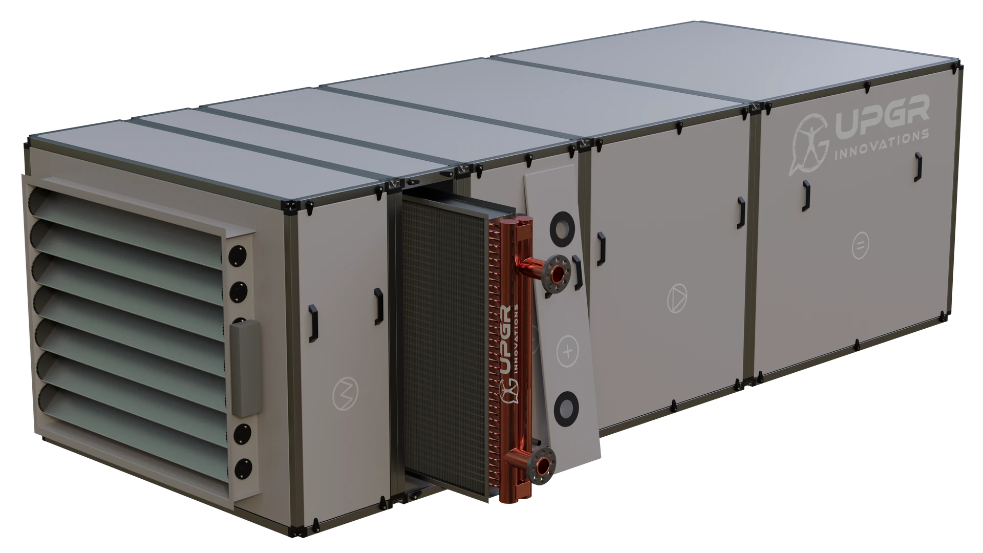
Access to a finned coil in a sectional AHU. Reserve space for removing the access panel and handling the coil; the actual removal procedure follows the equipment documentation.
- Access opening
- Provides access to the coil section.
- Finned coil
- The removable assembly must fit through the access opening and be handled with suitable support.
- Headers and connections
- Check disconnection requirements and available service space before removal.
A guide to equipment and selection; the final configuration and performance require project-specific confirmation.