Finned face
The example states 1280 × 690 mm. This is not the full envelope with frame and projecting connections.
By task
A new coil for a specified duty or a configuration made to an agreed drawing. Define the installation constraints, materials and results to be confirmed before manufacture.
FROM THE UPGR LIBRARY
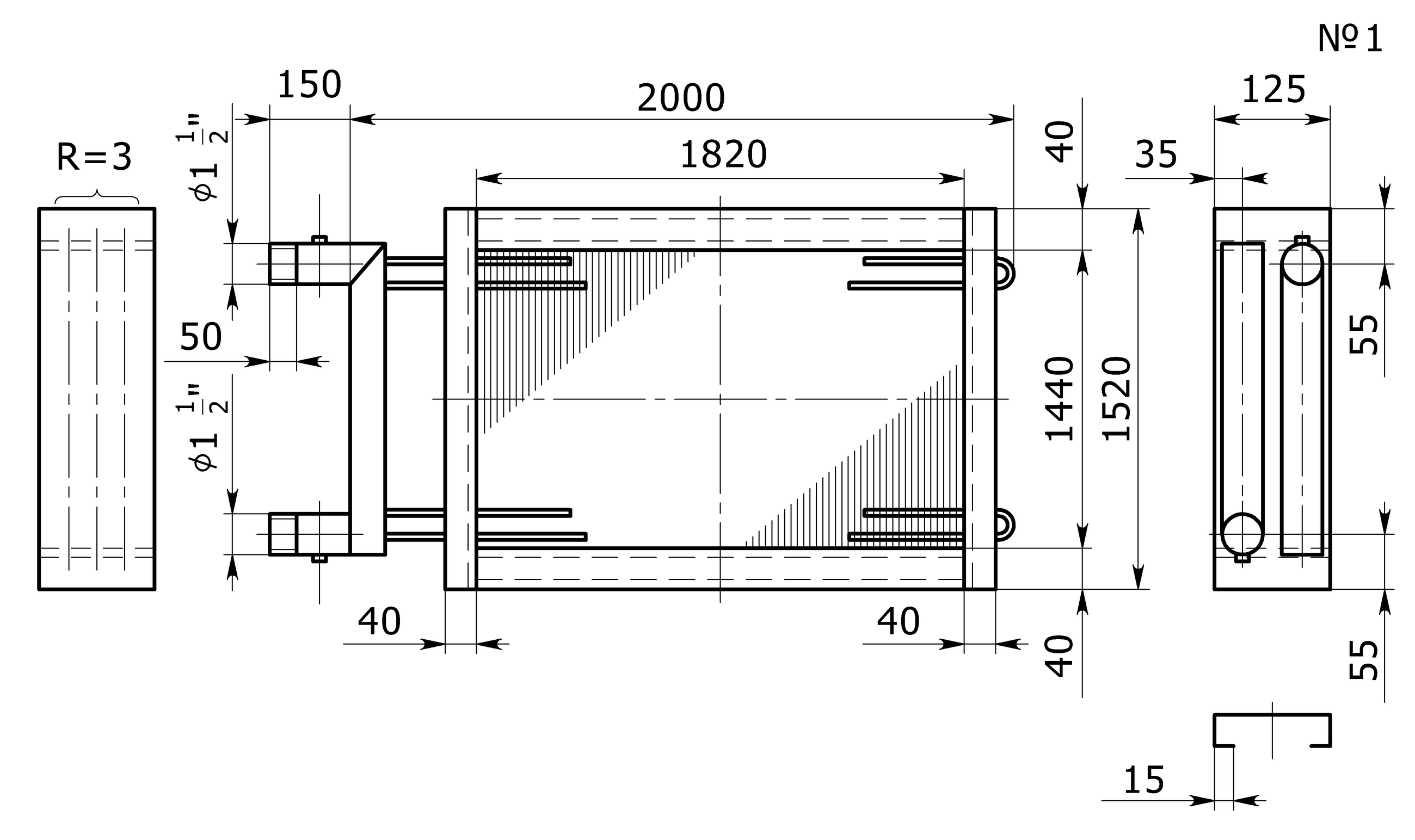
These existing archive examples show how face dimensions, overall dimensions and connections are recorded. Dimensions belong to the illustrated examples; the drawing for your order is agreed separately.
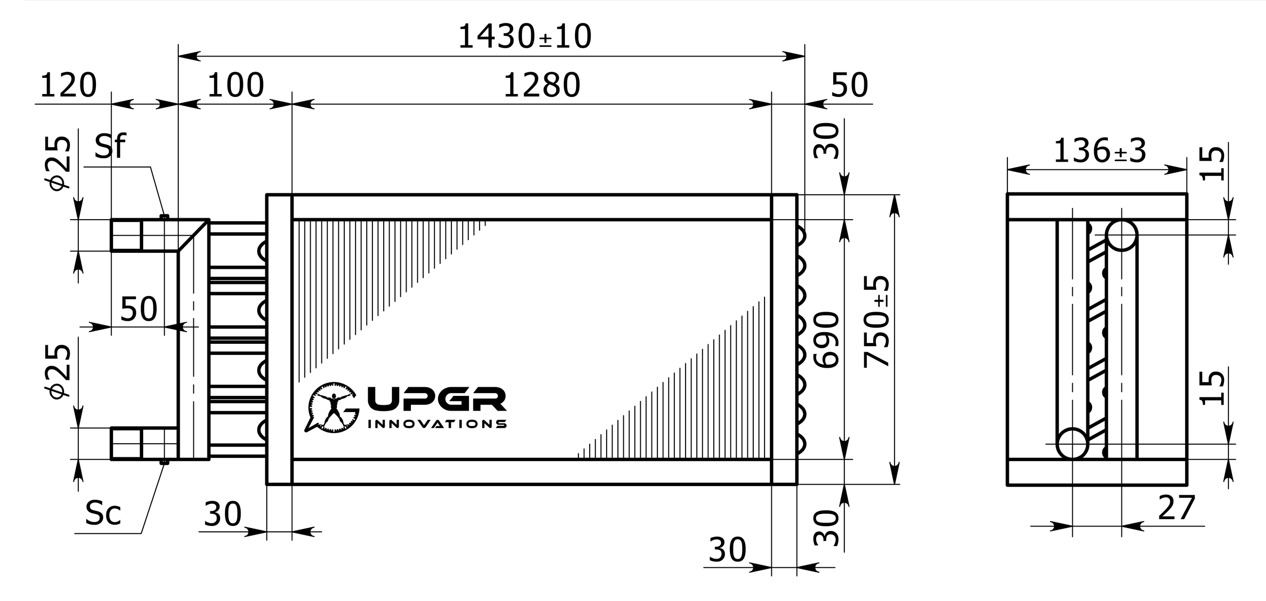
The example states 1280 × 690 mm. This is not the full envelope with frame and projecting connections.
750 ± 5 mm and 136 ± 3 mm are dimensions of this example. Check their extension lines and reference surfaces before comparing an opening.
The drawing shows Ø25, but connection type, position, function and viewing direction must also be agreed. Do not derive missing coordinates by measuring pixels.
DRAWING AND SPECIFICATION
This educational schematic helps you read dimensions and prepare measurements. The manufacturer drawing must also identify the configuration, materials, tolerances and revision.
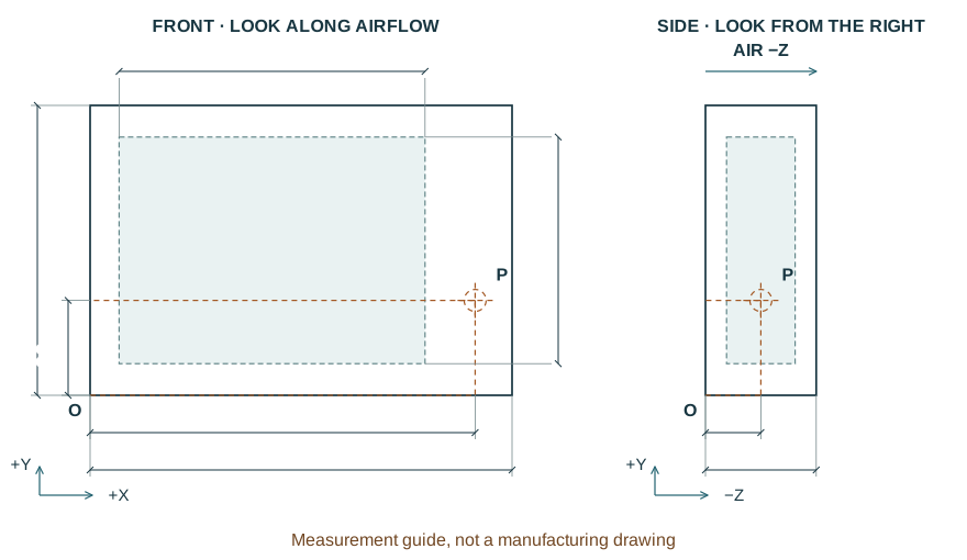
Full width, height and depth including projections. Check the opening and the path needed to remove the coil.
Dimensions of the finned block only. Do not substitute the frame or AHU casing dimensions.
Offsets from one stated datum. Each connection also needs its own position, diameter, connection type and function.
Modine DX Coils, page 3, Figure 6: dimensional enquiry data. Aerofin General Products Catalog, printed page 3: orientation and ordering information. These illustrate document content, not the specifications of the offered product.
Modine · DX Coils · PDF ↗Aerofin · General Products Catalog (2003) · PDF ↗REVIEW THE RESULT
State the drawing number and revision, airflow direction and dimensional datums. Record the envelope, finned face, fixings and connection positions separately, and explicitly agree mandatory dimensions and permitted tolerances.
Link the drawing to the working fluid, design duty and component-level material specification. Identify what the manufacturer may change during selection and what must remain fixed; reflect changes in the agreed revision.
Before manufacture starts, agree the supply scope, required checks and documents demonstrating compliance with the specification. The expected package comprises an accepted drawing, specification and agreed verification results; the selected manufacturer confirms the applicable scope.
For new equipment, start with the coil's intended function and project constraints. If the enquiry is based on an old coil, photographs or a sample, replacement identification is needed first. Separating these cases clarifies which parameters have been specified by the designer and which still need to be established from the existing product.
The drawing, duty and assembly description must refer to the same construction. Record dimensions, connections, materials and constraints with their source and document revision. Separate mandatory requirements from preferences. Where a parameter is to be determined during selection, state that explicitly rather than filling an unknown value from a similar-looking product.
IN PRACTICE
Separate the interfaces that cannot change from parameters that can be optimized and data still to be confirmed.
Opening, connections, duty and acceptance criteria.
Permitted geometry and material alternatives.
Unknown inputs, source drawing revision and quantity.
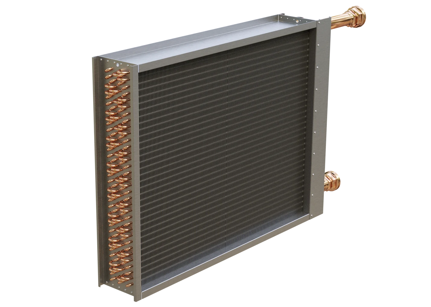
The generic coil image is an illustration of the product class, not a photograph of a completed custom order.
For a production enquiry, state the quantity, intended use and expected documentation and verification scope. The enquiry itself does not establish material availability, manufacturing capability or production repeatability. The specific construction, supply boundaries and verification method need to be agreed before a decision. Manufacturing to documentation does not imply official OEM status.
SELECTION INPUTS
Define operating conditions first. The input checklist above describes the data needed for this application. The enquiry form adapts to the selected duty; it does not calculate a coil rating.
Add the equipment nameplate, photographs, overall and finned dimensions, airflow direction, connections and access constraints. Matching the envelope alone does not confirm performance or compatibility.
Separate fixed interfaces from dimensions open to change. Attach the current drawing revision, duty points, material requirements, quantity and acceptance criteria. Manufacturing feasibility is confirmed for the specific specification.
Final performance, materials and compatibility require a project-specific selection and an approved drawing.
No. A manufacturer must confirm the feasibility of the specific geometry and duty. A general enquiry, or limits documented for another product, does not provide that confirmation.
Start with the replacement process: identification, photographs, available markings and measurements. Documentation can then be developed through clarification; a physical sample alone does not make the specification complete.
No. A drawing defines product requirements. Origin, official status and compatibility are separate claims, each requiring its own supporting evidence.