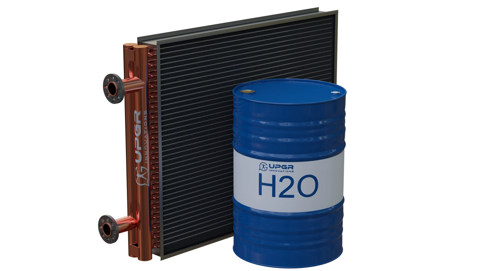
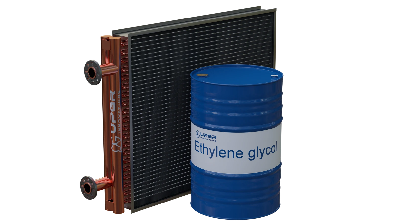
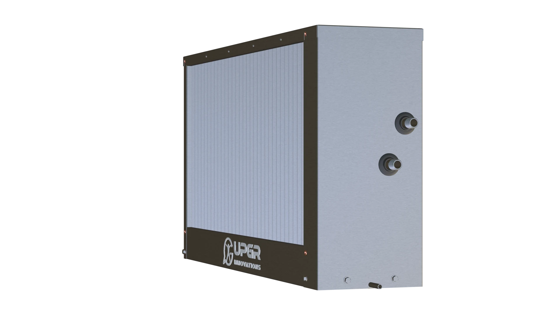
By working fluid
What flows inside the tubes?
In this exampleWater
All fluid groups and guides
- Water
- Water–glycol solution
- Refrigerant
HVAC · FINNED-TUBE COILS
The right coil starts with your operating conditions.
Heating and cooling coils for air handling units, refrigeration systems and equipment manufacturers. Start with a duty, an existing coil or your own drawing.
Have only photos or a nameplate? You can start with those.
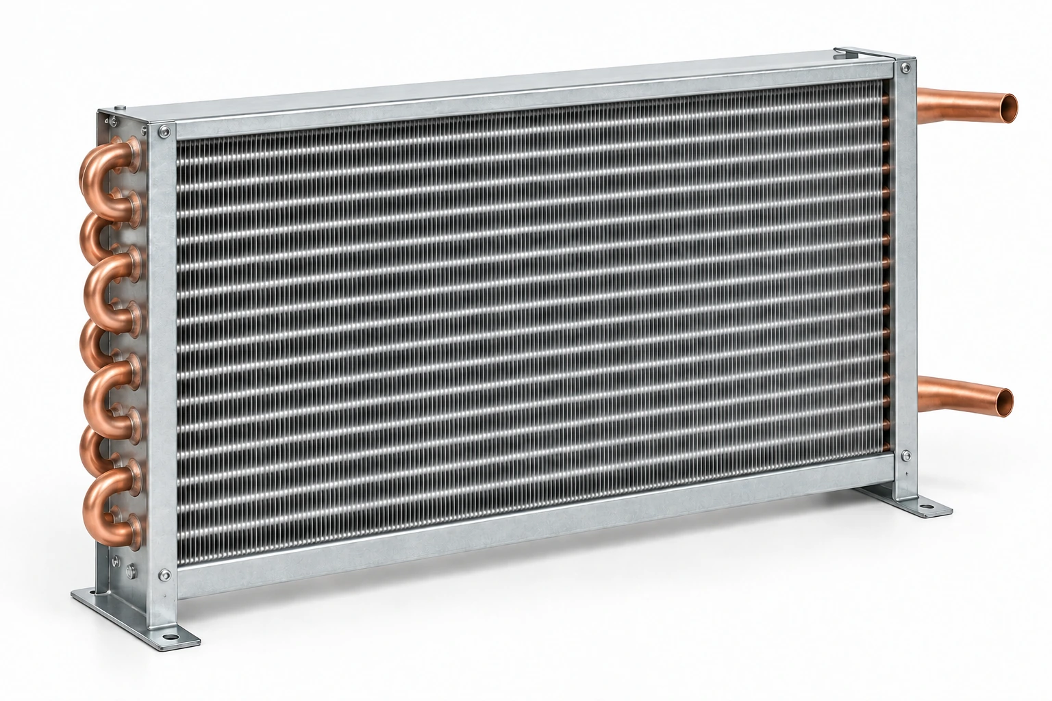
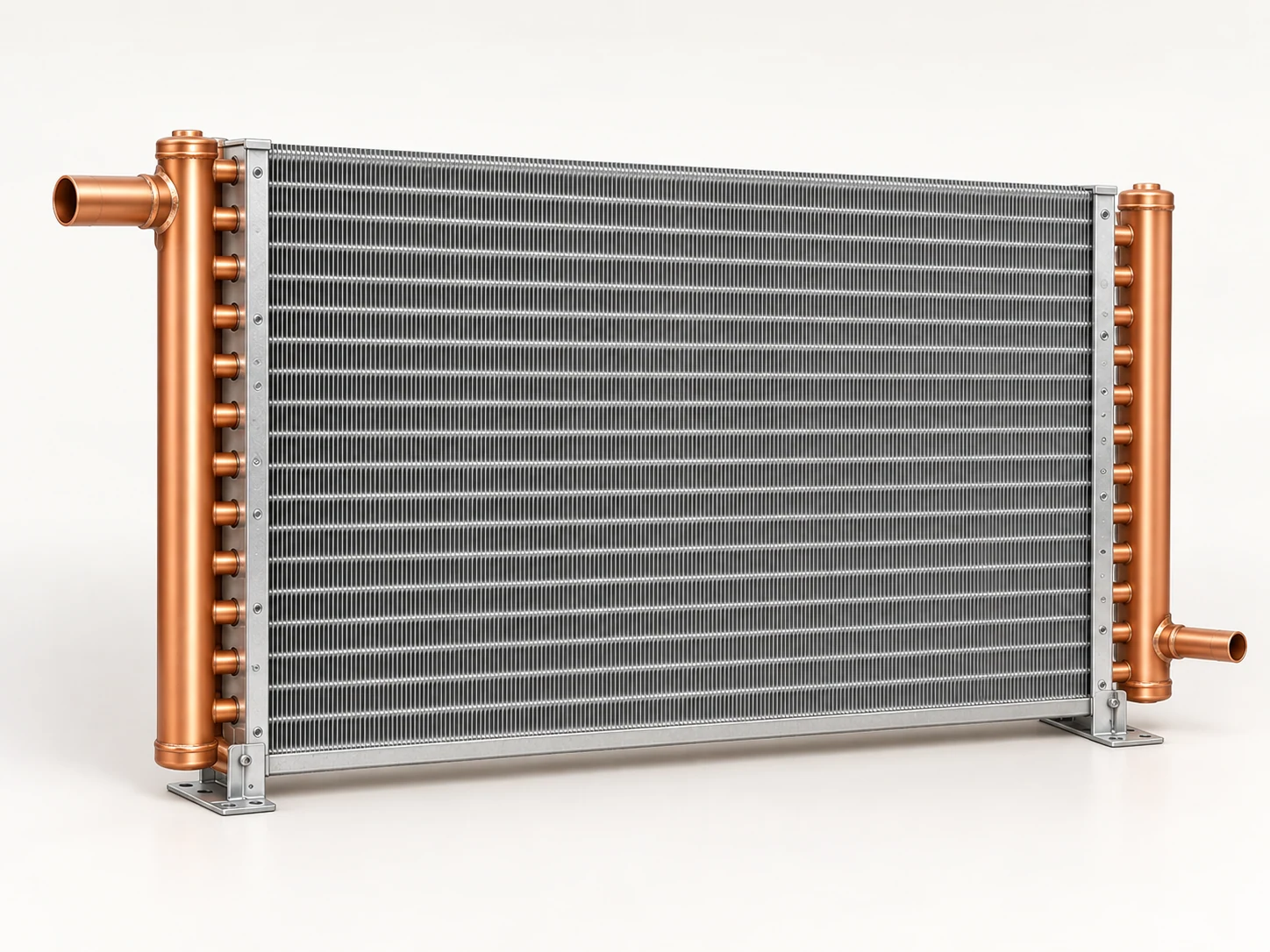
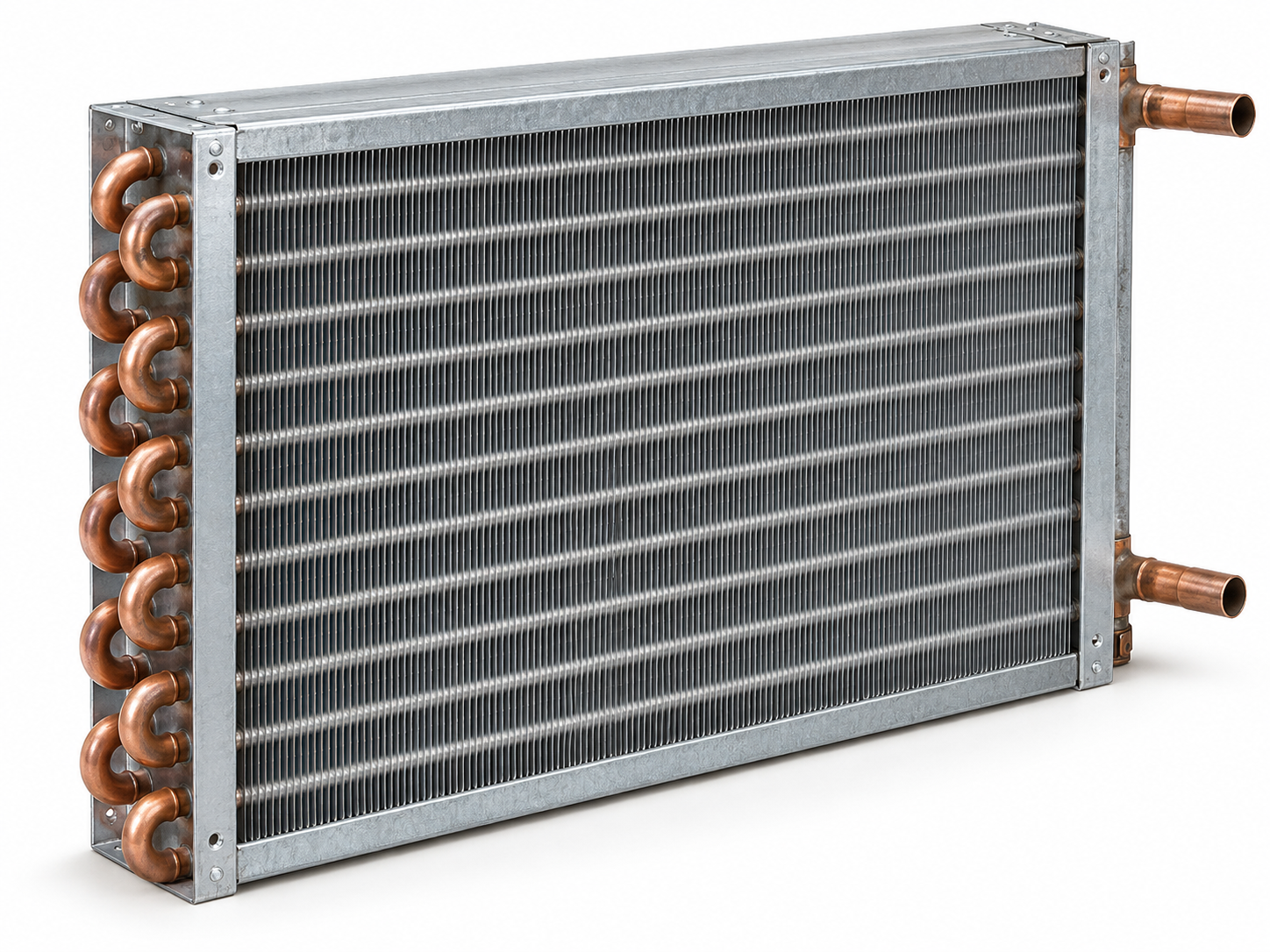
CuAl describes a finned-tube construction with copper tubes and aluminium fins. Heat passes between the internal fluid and air through the tube wall and fin surface. The same construction serves different duties and equipment: classify the fluid, thermal function and installation separately.
These three classifications are independent: for example, water is a fluid, air cooling is a duty, and an AHU is equipment. Piping assemblies and selection or replacement are separate practical topics.
What flows inside the tubes?
In this exampleWater
Which heat-transfer task does the coil perform?
In this exampleAir cooling
Where is the coil installed?
In this exampleAir handling unit
Example: water + air heating + supply AHU describes one coil from three perspectives.
Choose the working fluid, function, equipment, piping assembly or task. Each link opens a dedicated guide with its own input checklist.
What flows inside the tubes? These guides cover water, glycol solution and refrigerant requirements. Choose the coil duty separately.
What must the coil do: heat or cool air, evaporate or condense refrigerant? These guides cover operating conditions and selection inputs.
Where is the coil installed? Start with the equipment type, then identify the heat exchanger, its duty and its connections.
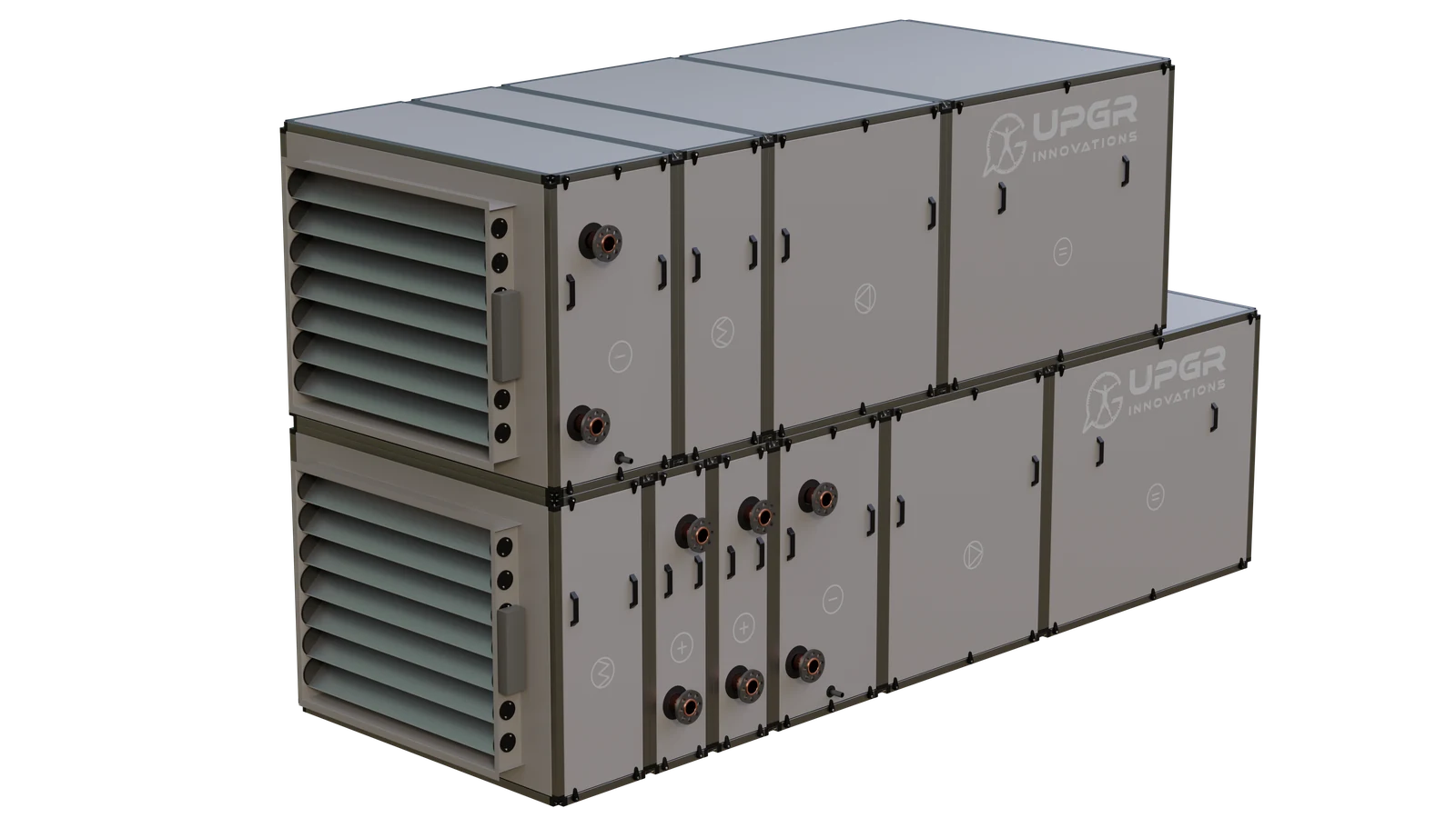 Heat exchange coils for air handling units
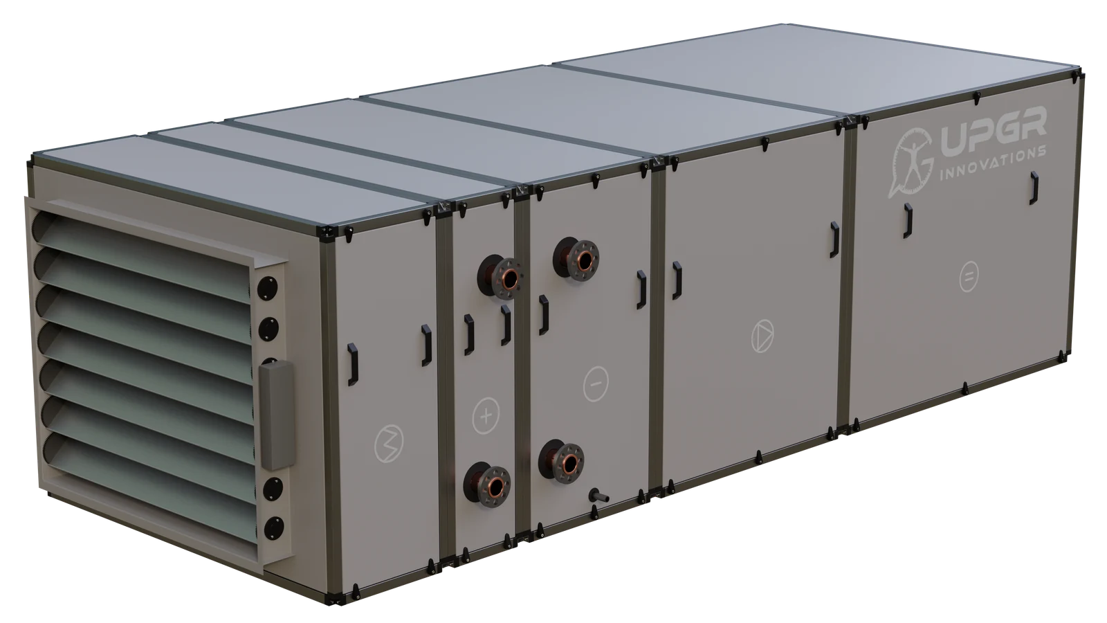 Coils for supply air handling units
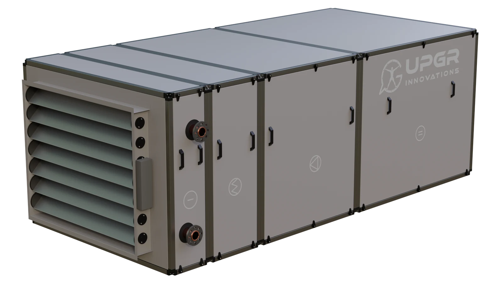 Coils for extract air handling units
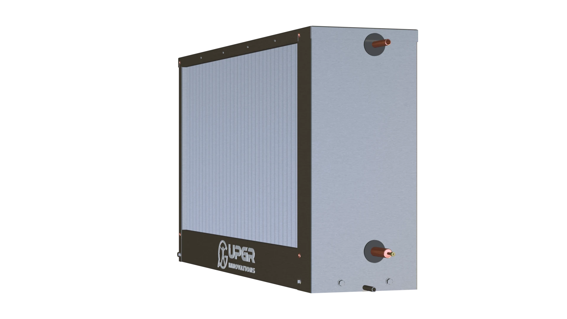 Air conditioner coils: identifying the heat exchanger
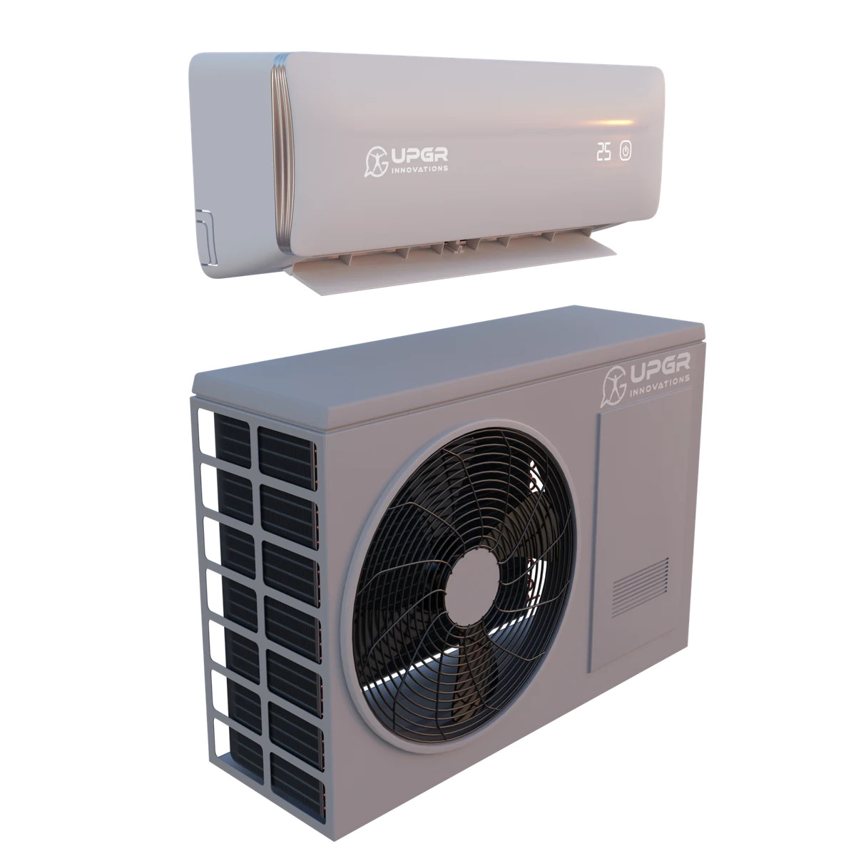 Replacement coils for split systems
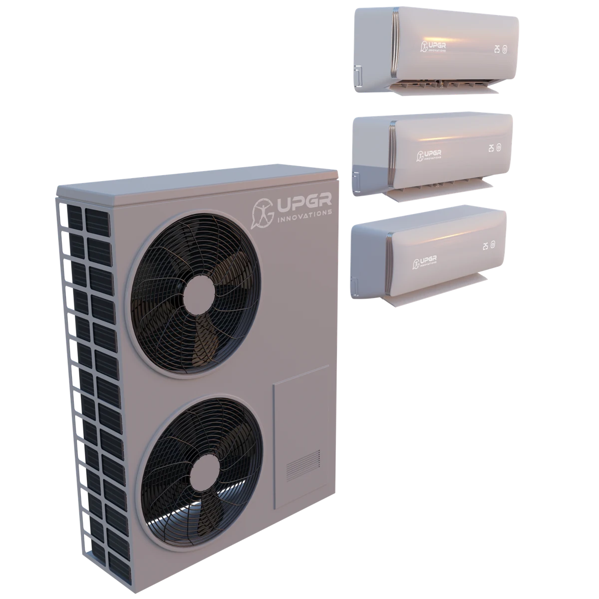 Replacement coils for multi-split systems
 Coils for rooftop units
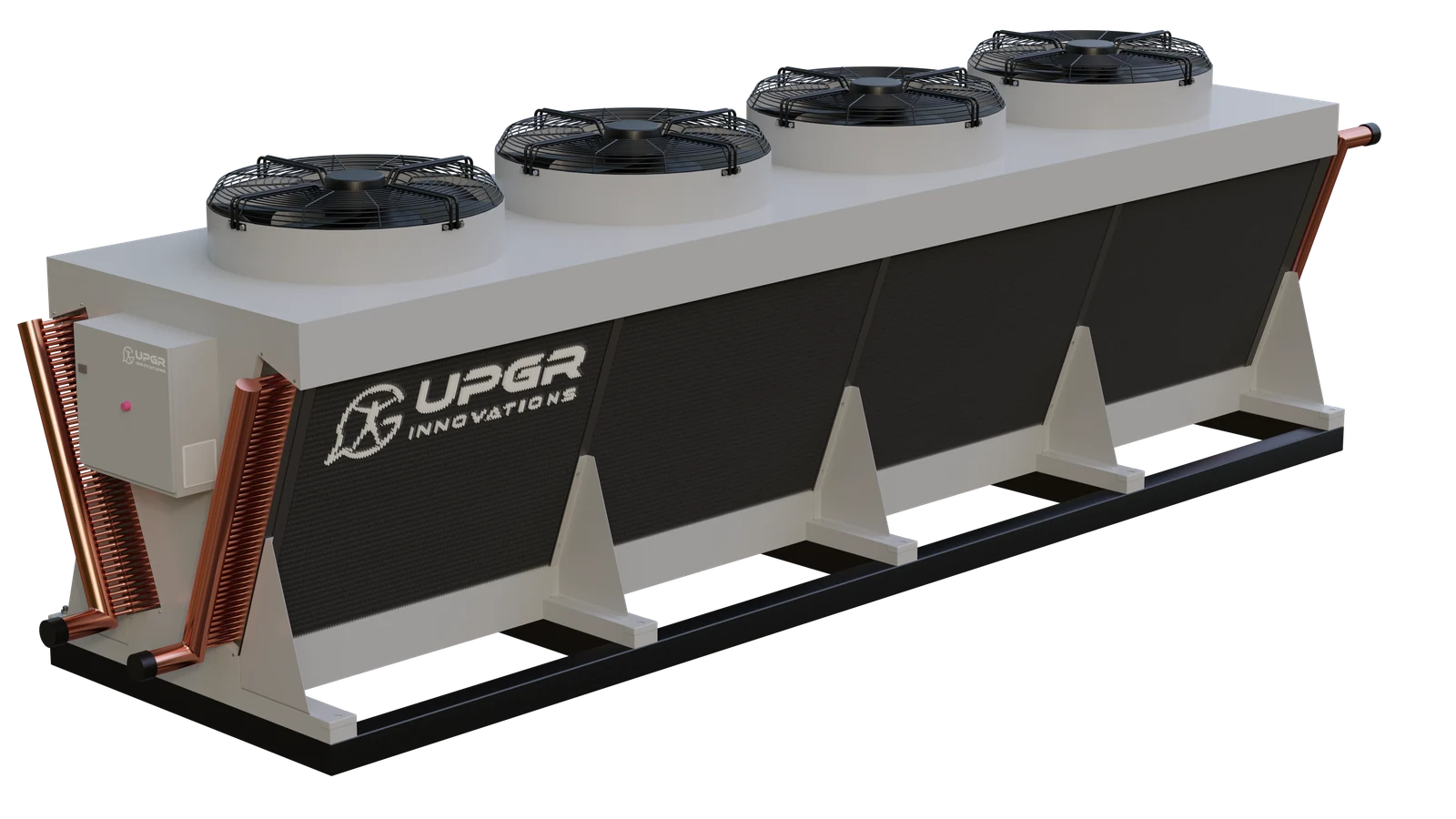 Air-side heat exchanger coils for chillers
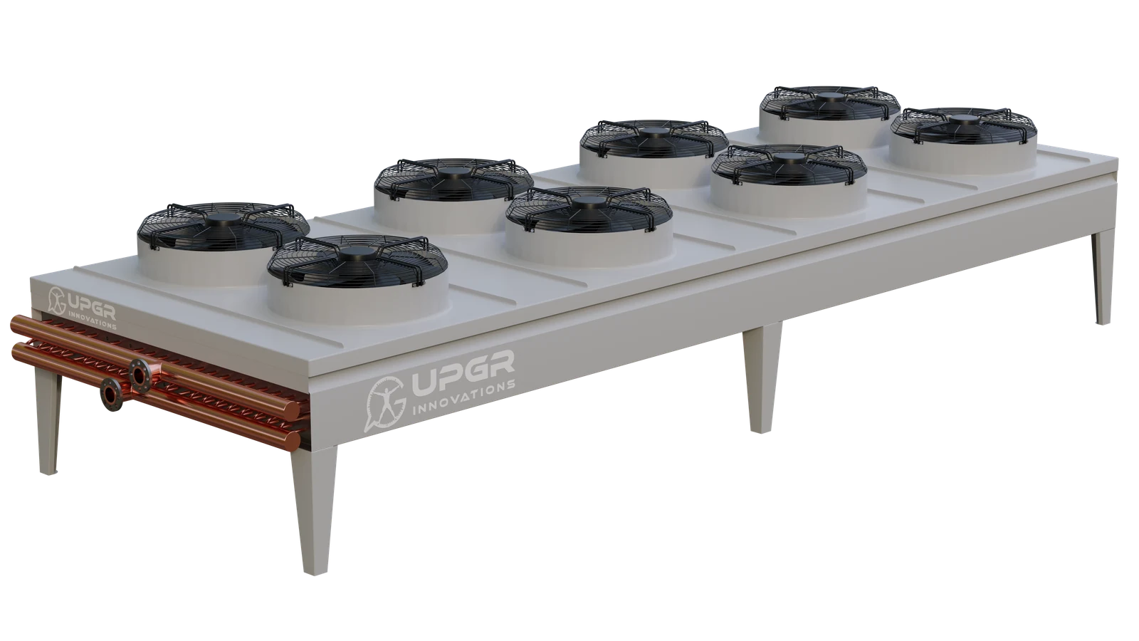 Coils for dry coolers
What is required alongside the liquid coil? A mixing assembly has its own circuit, component list and supply scope.
What needs to be done: select a coil, replace an existing one or prepare manufacture? These guides cover the steps and documents.
Illustrations explain construction. Dimensions and materials are defined for each model.
Select a coil for a known airflow, temperature duty and available space.
Prepare a selection requestMatch the installation envelope, connections and required performance of an existing unit.
See the replacement checklistDiscuss a drawing, a prototype or repeated production for your equipment.
Describe an OEM project01 / APPLICATIONS
Copper tubes carry the working fluid; aluminium fins increase the air-side heat transfer area. The application determines the circuit, dimensions and selection inputs.
For heating supply air in ventilation and air handling units.
Start with airflow, entering air temperature and water or glycol temperatures.
Choose this applicationFor cooling air, with condensate drainage when the coil also removes moisture.
Include entering air humidity and the required leaving air condition.
Choose this applicationFor direct-expansion cooling in ventilation and refrigeration equipment.
Specify the refrigerant, evaporating conditions and required capacity.
Choose this applicationFor transferring heat from refrigerant to ambient air.
Specify refrigerant, condensing conditions, ambient temperature and heat rejection duty.
Choose this applicationFor rejecting heat from a water or glycol loop to outdoor air.
Confirm the fluid and concentration, fluid temperatures, outdoor air and airflow.
Choose this applicationCompare the complete unit, access to the coil and an exploded view. These examples show the relationship between the equipment casing and the heat-transfer section.
The casing guides supply air through its sections. A water, glycol or DX coil heats or cools the air; access panels and removable elements allow servicing.
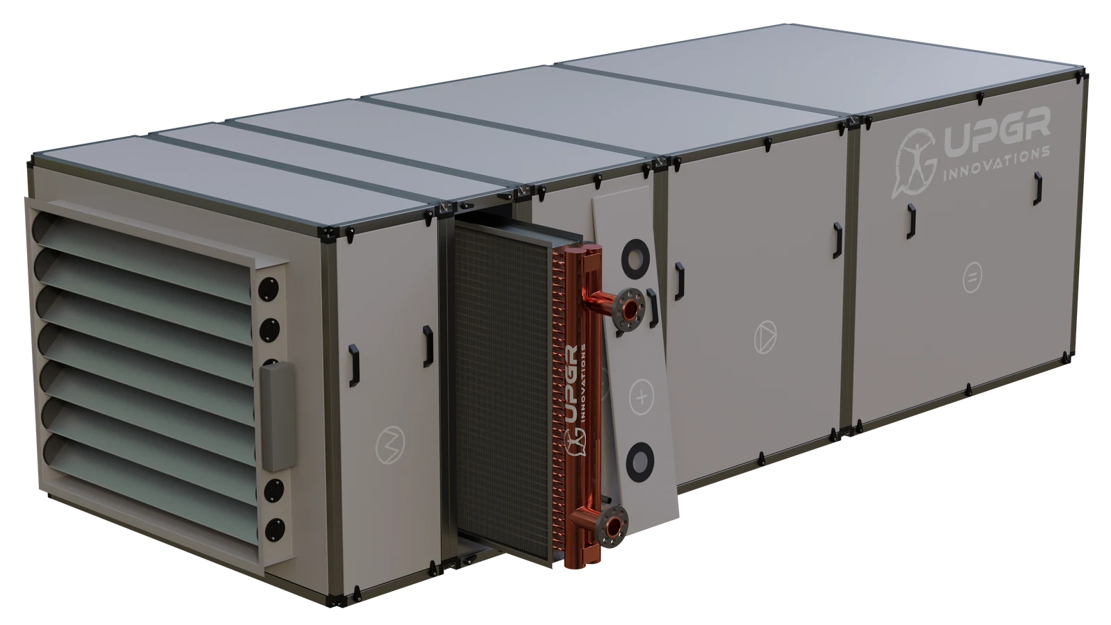
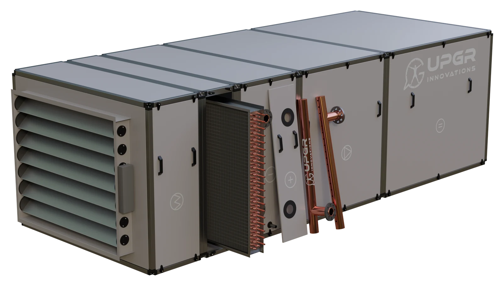
An extract air path may contain a coil for heat recovery or a separate air-treatment duty. Its function is defined by the air and fluid circuits.
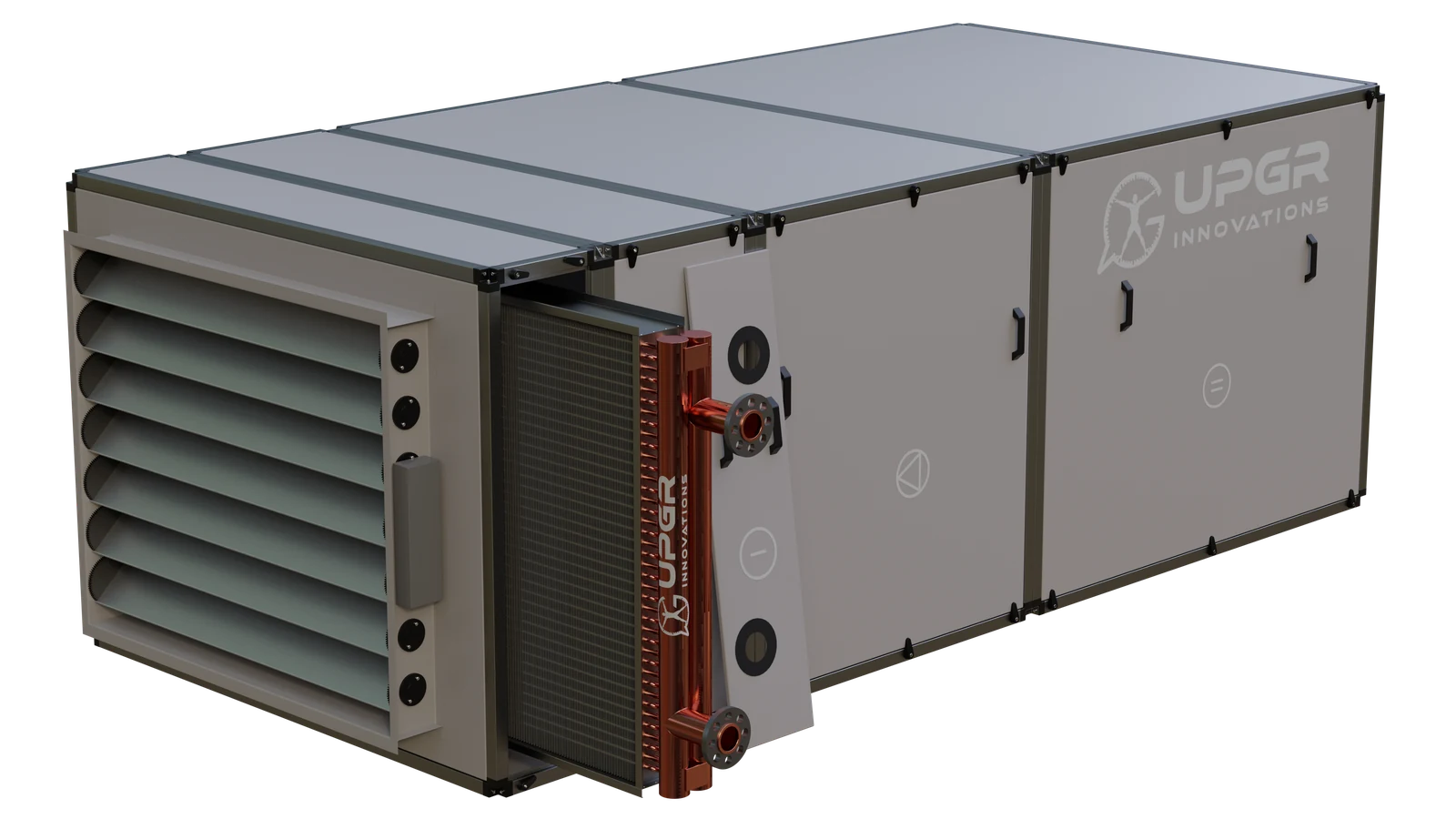
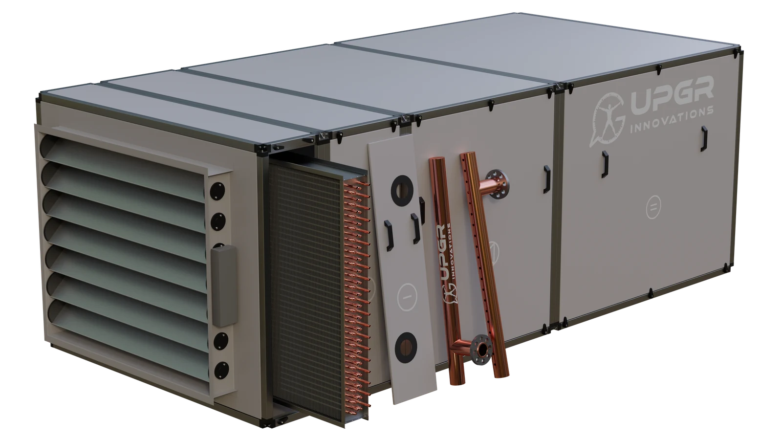
The two-level arrangement illustrates separate air paths. Heating, cooling and recovery coils have distinct duties. A run-around recovery system uses coils connected by a liquid loop; plate and rotary air-to-air exchangers use a different construction.
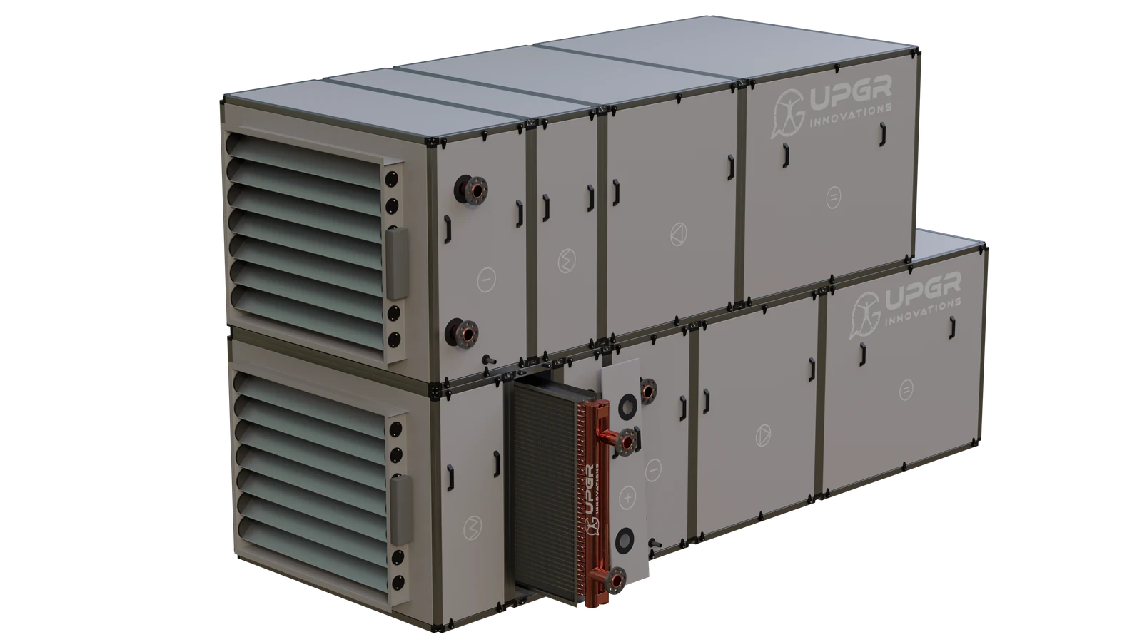
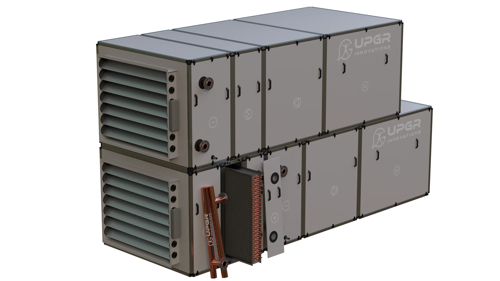
CuAl describes a finned-tube construction with copper tubes and aluminium fins. Heat passes between the internal fluid and air through the tube wall and fin surface. The same construction serves different duties and equipment: classify the fluid, thermal function and installation separately.
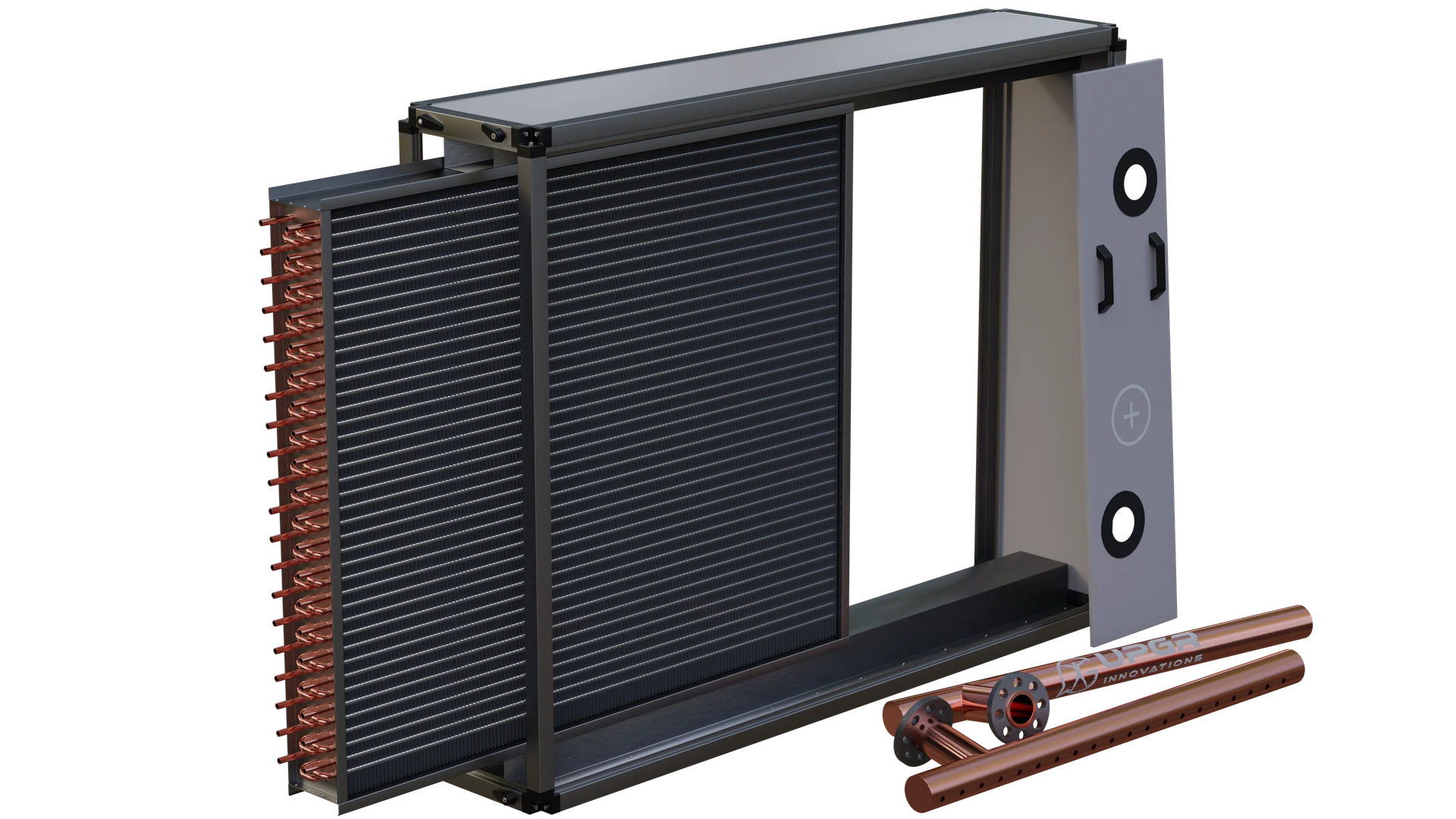
Read the following parts as a typical CuAl coil anatomy. Actual circuiting and accessories vary with the equipment and duty.
Heat-transfer core
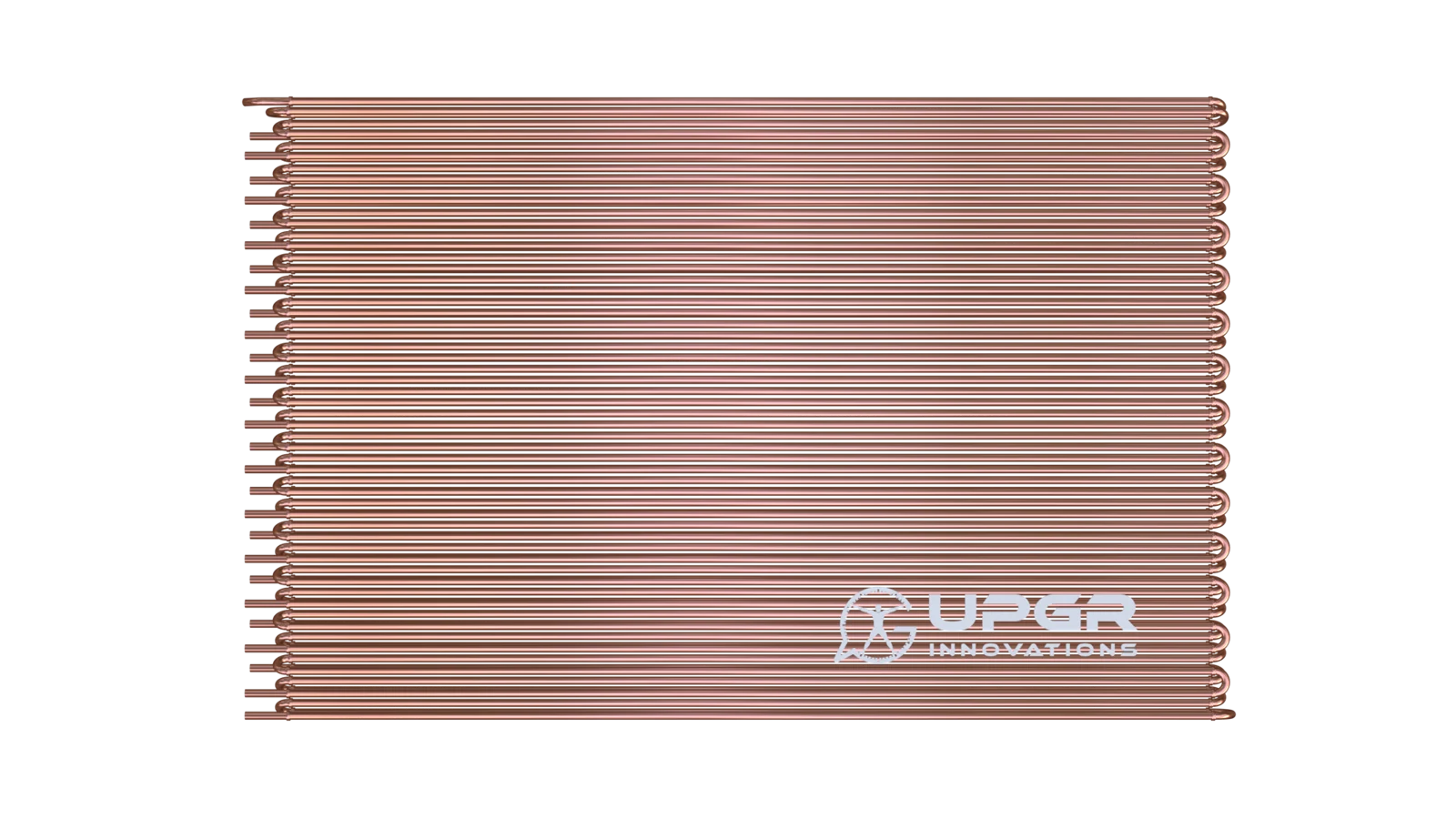
Channels carrying the working fluid through the finned core.
Separate the fluid from air and conduct heat to or from the fins.
Core element of a CuAl finned-tube coil.
Leak traces, corrosion or visible damage.
Heat-transfer core
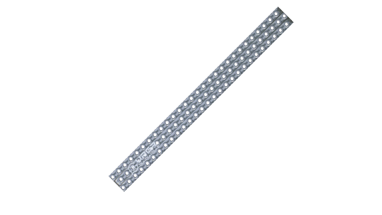
Thin metal sheets in thermal contact with the tubes.
Enlarge the surface exchanging heat with air.
Core element; spacing and profile vary.
Dirt deposits, damaged passages or corrosion.
Depends on circuit and construction
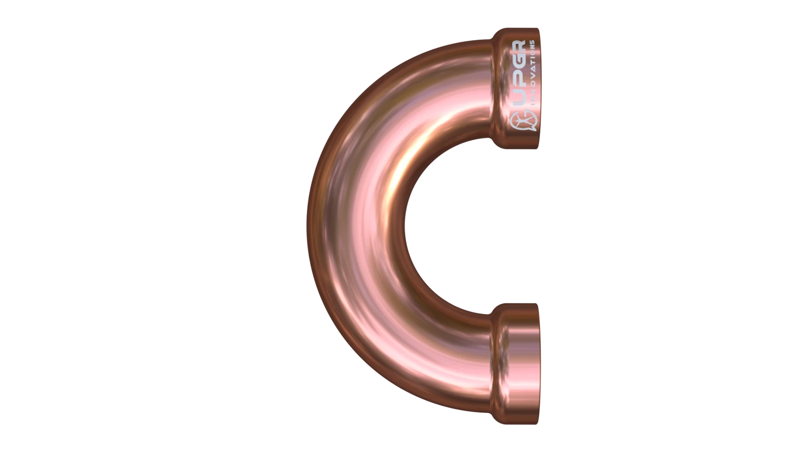
Curved tube sections connecting successive passes.
Turn the flow and form the coil circuit.
Layout-dependent; an integral hairpin and a separate return bend are different constructions.
Damaged bends or leakage at joints.
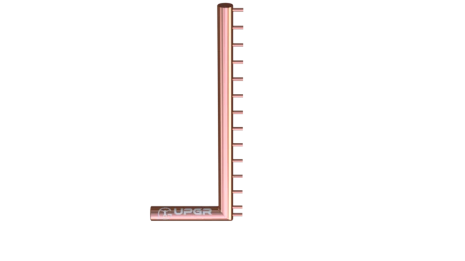
Depends on circuit and construction
Manifolds linking multiple tube circuits to external connections.
Distribute or collect the working fluid.
Arrangement depends on circuiting; headers are not identical to a DX distributor.
Corrosion, joint damage or leak traces.

Depends on circuit and construction
End plates and supporting casing around the core.
Support the core and provide mounting interfaces.
Common; casing styles include end-plates-only constructions.
Deformation, corrosion or damaged mountings.
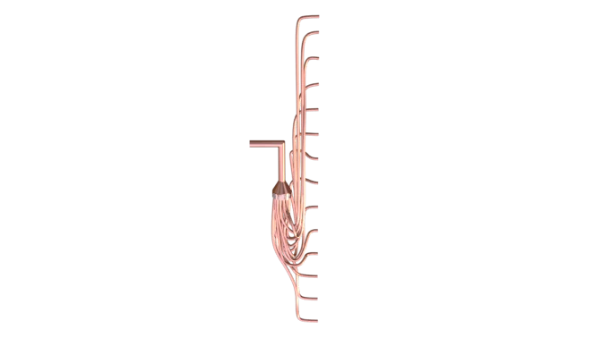
Where required by the duty
A device feeding the parallel circuits of a DX evaporator.
Divides refrigerant between the selected coil circuits.
DX-specific where used; the expansion valve has a separate function.
Damaged small tubes or leakage signs require diagnosis.
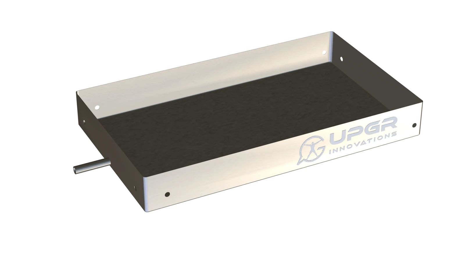
Where required by the duty
A collection surface beneath a coil that produces condensate.
Collect and remove condensed water.
Needed for wet cooling; often part of the equipment section.
Standing water, deposits, corrosion or leakage.
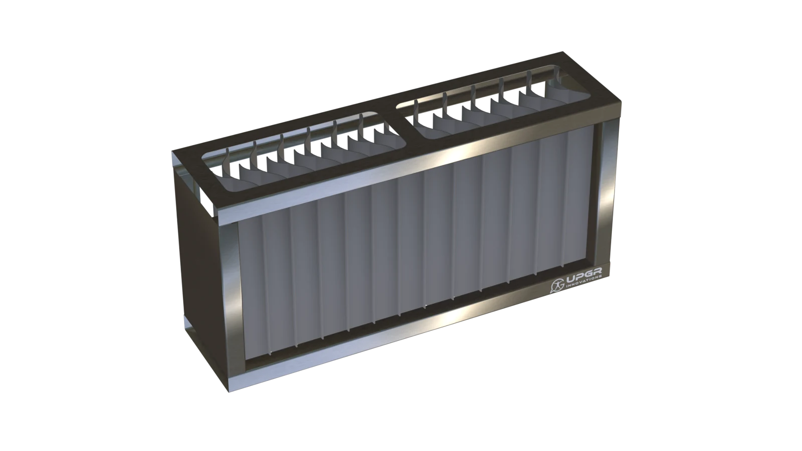
Where required by the duty
A downstream separator for droplets carried by the airflow.
Intercepts droplets and lets collected water drain.
Conditional on carryover risk and equipment design; not every cooling coil has one.
Contamination, damage or water carryover.
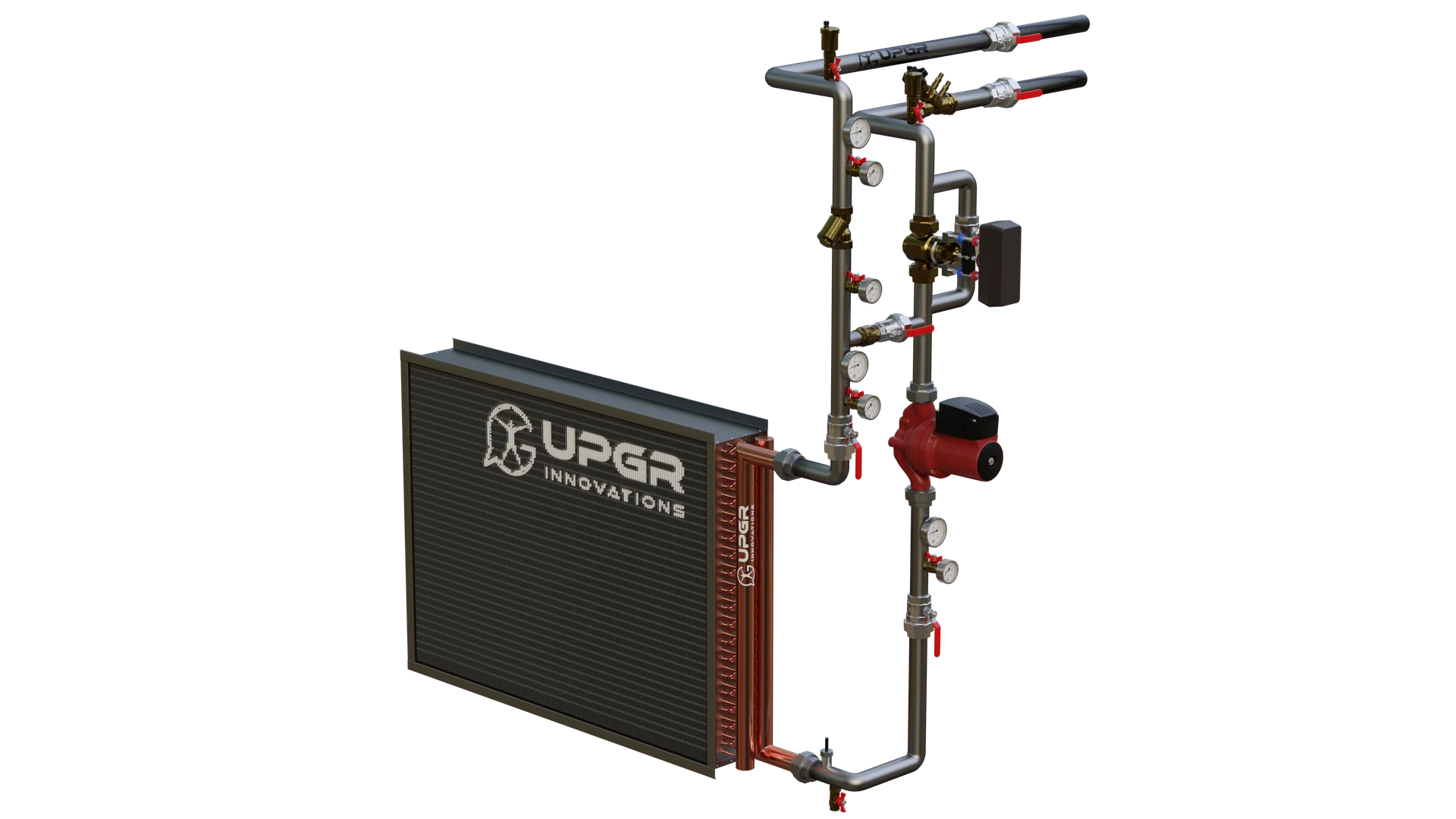
External piping
A separate piping package with valves and, where specified, a pump.
Controls fluid delivery and connects the coil to the system.
External to the finned core; component list follows the circuit design.
Leaks or control faults are system issues, not proof of coil damage.
Condition signs help identify what needs inspection; they do not identify the fault by themselves. Service methods and intervals follow the equipment manual.
These applications concern finned coils that exchange heat with air. Identify the equipment, the coil's function and the medium inside its tubes separately; then confirm the materials and allowable operating conditions for the actual unit. The name of a heat pump, dryer or greenhouse system does not mean that every heat exchanger in it has copper tubes and aluminium fins.
Room-temperature control starts with the fan-coil section: water heats or cools the air passing through it.
In a hydronic fan coil, the coil transfers heat between the room air and water. Cu-Al constructions are used in this equipment, but replacement still depends on the exact model. A two-pipe unit uses its water circuit for the selected heating or cooling duty; a four-pipe arrangement has separate heating and cooling circuits. For cooling, check moisture removal and condensate drainage as well as the air temperature.
Additional selection data Unit model; two- or four-pipe arrangement; fan speed and airflow; water temperatures and flow for each duty; total and sensible cooling loads; entering-air humidity; coil dimensions, connection side and drain-pan position.
Heating and cooling use different operating modes of an air coil. In a reversible heat pump, it can change between evaporator and condenser duty.
A reversible air-source heat pump can use the same air coil as an evaporator in one operating mode and a condenser in another. Cu-Al versions exist, but the replacement must match the unit's refrigerant circuit and operating modes. An air coil and a refrigerant-to-water heat exchanger are different components; matching one heating-capacity figure does not establish interchangeability.
Additional selection data Unit model and circuit diagram; refrigerant; heating and cooling design points; evaporation and condensation conditions; required pressure rating; circuit arrangement and connections; defrost mode, meltwater drainage and installation orientation.
Warm air at the opening comes from a water-heated section. The fan and outlet nozzle then form the air-curtain jet.
In a water-heated air curtain, a coil heats the air discharged towards the doorway. Select the coil together with the airflow produced by the fan and outlet. Identify the exact water-heated model from its nameplate and documentation, then check access for removing the coil and the space available for valves and connections.
Additional selection data Exact water-heated model; airflow at the selected fan setting; water supply and return temperatures; heating load and allowable water pressure drop; coil dimensions and connection positions; control valve and frost-protection requirements.
Cooling a storage room means removing heat from its circulating air. The air-cooler section does this with a refrigerant or an intermediate coolant.
The room air cooler removes heat from circulating air. Identify whether its tubes carry evaporating refrigerant or a chilled secondary fluid before specifying a replacement. Moisture, frost and the defrost arrangement affect the coil selection and drainage. A cold-room application by itself does not establish the suitability of copper tubes, aluminium fins or a particular coating.
Additional selection data Room temperature and product duty; heat and moisture loads; refrigerant or secondary-fluid specification; operating temperatures and required pressure rating; fin spacing; airflow and air distribution; defrost method, drain arrangement and cleaning requirements.
The required air conditions in a technical room depend on the actual cooling circuit. Water coils and direct-expansion evaporators need different selection data.
Precision cooling equipment can use a chilled-water air coil or a direct-expansion evaporator. Start with the actual circuit: these sections require different input data and connections. For a server room or equipment space, distinguish the sensible heat load from the moisture-removal duty and identify any separate reheat section. The term precision air conditioning does not specify a Cu-Al construction.
Additional selection data Unit model and cooling scheme; sensible and total loads; entering and required leaving-air conditions; airflow and available fan pressure; water conditions or refrigerant cycle data; condensate drainage; section dimensions and service access.
Drying conditions depend on the section's job: a water heater warms the air, while refrigerant sections in a heat-pump dryer also remove moisture and return heat to it.
A hot-water air heater can heat recirculated air in a drying chamber. A heat-pump dryer also uses refrigerant coils to remove moisture and return heat to the air. These are different functions, even within one machine. For timber or another product, confirm the drying stages and the actual heat source before considering Cu-Al; the chamber name is not evidence of material compatibility.
Additional selection data Product and drying stages; air temperature, humidity and circulation at each stage; moisture to be removed; actual heating medium or refrigerant; maximum operating temperature; airborne contaminants; cleaning access, dimensions and connection positions.
A condensing dehumidifier removes water by cooling the air, then reheats it. Greenhouse equipment may also have a separate water heating or cooling section.
In a condensing dehumidifier, air is cooled at the evaporator to collect water and then reheated at the condenser. A desiccant unit has a different moisture-removal process: identify its air-treatment coils separately from the rotor and regeneration heater. Greenhouse equipment may also have a water-fed heating or cooling section. Confirm which component needs selection and whether its materials are specified as Cu-Al.
Additional selection data Dehumidification method and section function; moisture load and target humidity; entering and leaving-air conditions; airflow; water or refrigerant conditions; condensate drainage; greenhouse airborne chemicals, cleaning products and required material protection.
The required process conditions define the air section's job. Identify the actual heater or cooler first, keeping the production process separate from the fluid circuit.
For a printing machine, conveyor or production line, first identify the actual component. An air heater, an air cooler and a liquid-to-liquid exchanger solve different tasks. This page applies where an air coil is required and its materials are confirmed. The product being manufactured does not necessarily flow inside the coil: distinguish the process, the air stream and the water, glycol or refrigerant circuit.
Additional selection data Machine and coil identification; process duty and operating cycle; both heat-transfer media; temperatures, flows and load range; allowable pressure drops and required pressure rating; contamination and cleaning method; fixed dimensions, connections and acceptance criteria.
These equipment-specific inputs supplement the common selection data below. Confirm the tube and fin materials, medium compatibility and allowable temperature and pressure with the manufacturer. State operating pressure, the required pressure rating and permitted pressure drops separately, with units. Include airborne contaminants and cleaning chemicals when defining material and coating requirements.
For equipment that contains other heat-exchanger constructions, use the wider application guide. It covers the full assembly and does not imply that every component is Cu-Al. Wider heat-exchanger application guide
A clear repair decision starts with the symptoms, evidence from the actual coil and a comparison of the two options.
Reduced heating or cooling is a symptom, not proof that the coil must be replaced. Record temperatures, airflow or fluid flow, changes in operating conditions, contamination and any visible damage. A leak requires separate identification of its location and cause.
Use these part illustrations to locate the area on your own coil. Photograph the actual condition and include the surrounding assembly.
Show the affected fin area and the corresponding tubes.
Include the connection, joint and surrounding material.
Show distortion, clearances and the path for removing the coil.
A damaged fin does not confirm a tube leak. Its location and cause require separate identification.
For the finned core, photograph damaged fins and the affected tube area. For headers and return bends, show the connection, joint and surrounding material. For the casing, record distorted mounting points, clearances and the direction in which the coil can be removed. Do not confuse a damaged fin with a confirmed tube leak.
Extent, cause and condition of the rest of the coil.
Accessible joints and suitability for the original duty.
Time out of service and required checks after the work.
Cleaning, fin straightening, tube or header work and replacement are different operations. The method depends on the design and condition.
Compare restoration and replacement using an inspection report: extent and cause of damage, remaining condition, accessible joints, suitability for the original duty, downtime and the required post-work checks. Fin straightening, tube or header work, cleaning and replacement are different operations; the appropriate method depends on the design and condition.
An agreed specification makes the finished coil checkable: define the design, the inspection requirements and the documents expected with the unit.
Drawing revision, circuit layout and materials.
Inspection requirements are agreed for the actual design.
Agree which documents are supplied; check that they refer to the ordered unit.
Library examples do not confirm that documents have been issued for a particular coil. The document set is agreed with the selected manufacturer.
Agree the drawing revision, circuit layout, materials, inspection requirements and supplied documents with the selected manufacturer. Drawings, selection reports, test records and an operating manual serve different purposes; examples from the library do not confirm that these documents have been issued for a particular unit.
A finned-tube coil combines tubes, fins, return bends, headers and a supporting casing. Manufacturing operations depend on the design and may include fin forming, tube preparation, tube-to-fin expansion, joining and casing assembly. A general process description does not specify the technology for every coil.
The operations depend on the design; this overview does not establish a factory process for every coil.
02 / ENGINEERING INPUTS
Capacity alone is not enough.
A selection connects thermal performance with the space and pressure drop available in the system. Provide known values; leave unknowns open for clarification.
Airflow in m³/h, inlet and target outlet temperatures in °C. For cooling, also humidity and allowable air pressure drop in Pa.
Fluid type, glycol concentration if used, operating temperatures and flow rate. State operating pressure and maximum permitted pressure drop separately, with units. For DX, give the refrigerant and cycle conditions.
Overall envelope and finned dimensions separately; connection sizes and positions, mounting points and the airflow direction.
Dust, moisture, cleaning access, corrosion exposure and freezing conditions affect the construction requirements.
Tube diameter, rows, fin spacing and circuiting are selection variables. More rows or tighter fins do not automatically make a better coil.
Unknown values can stay blank. Opening the form does not change the information you have entered.
03 / REPLACEMENT
A similar appearance is not enough. Document the installation and the working conditions before confirming a replacement.
Overall view, nameplate, connections, mounting and any damage. Include the surrounding installation space.
Width, height and depth of the complete assembly and finned block; connection centres, diameter and projection.
One worksheet keeps the overall dimensions, finned dimensions and connection references together.
Open the blank measurement worksheetShow airflow, fluid inlet and outlet, and the viewing direction used to describe left or right connections.
Original selection sheet or drawing if available; temperatures, airflow and fluid. Explain what needs to change.
A photo helps identify the construction. Final manufacturing dimensions require a checked drawing or measurements.
FROM THE UPGR LIBRARY
These archive examples explain how face dimensions, overall dimensions and connections are recorded. They are not manufacturer-approved drawings for selection or manufacture. Dimensions belong only to the illustrated examples; your model and order require a separately agreed drawing.
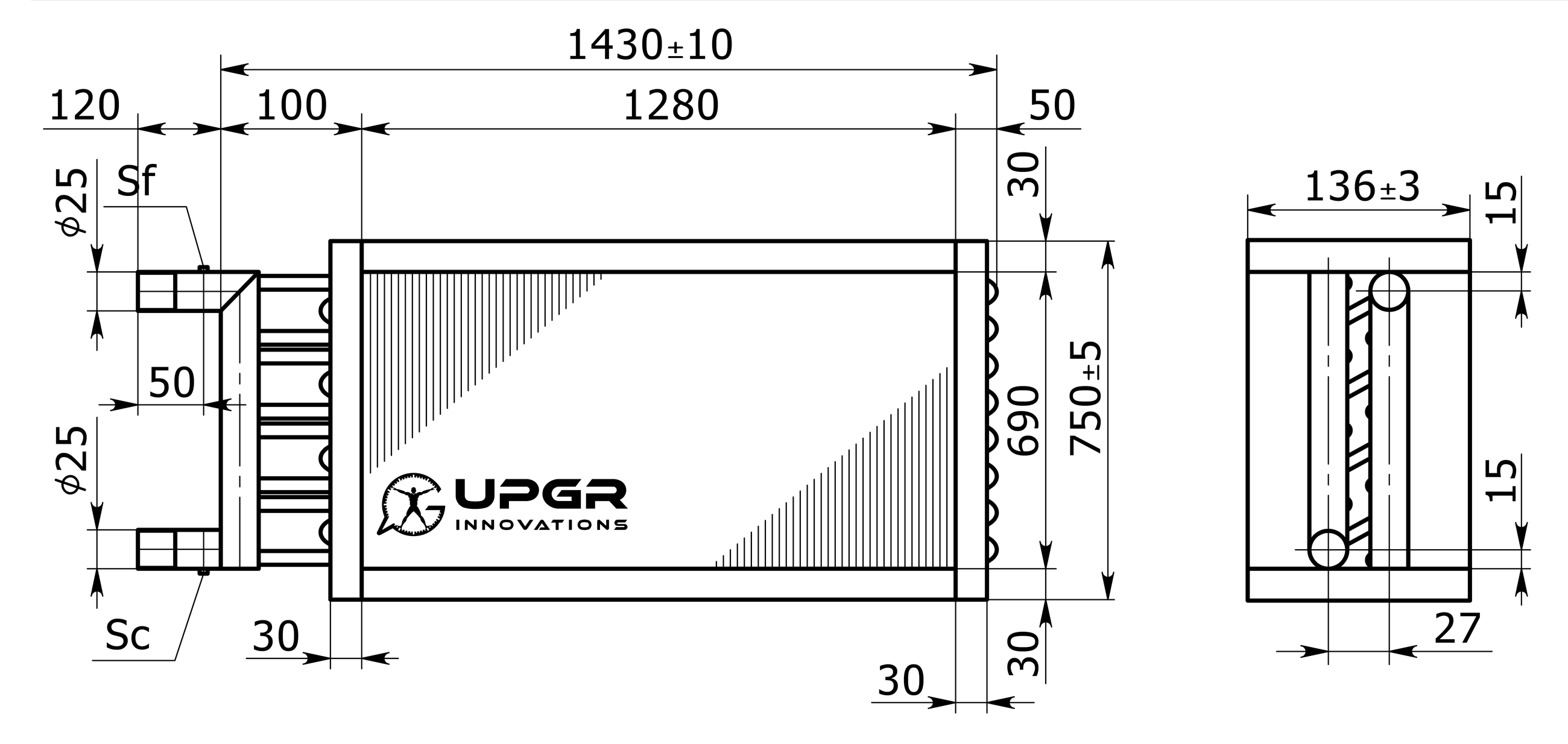
The example states 1280 × 690 mm. This is not the full envelope with frame and projecting connections.
750 ± 5 mm and 136 ± 3 mm are dimensions of this example. Check their extension lines and reference surfaces before comparing an opening.
The drawing shows Ø25, but connection type, position, function and viewing direction must also be agreed. Do not derive missing coordinates by measuring pixels.
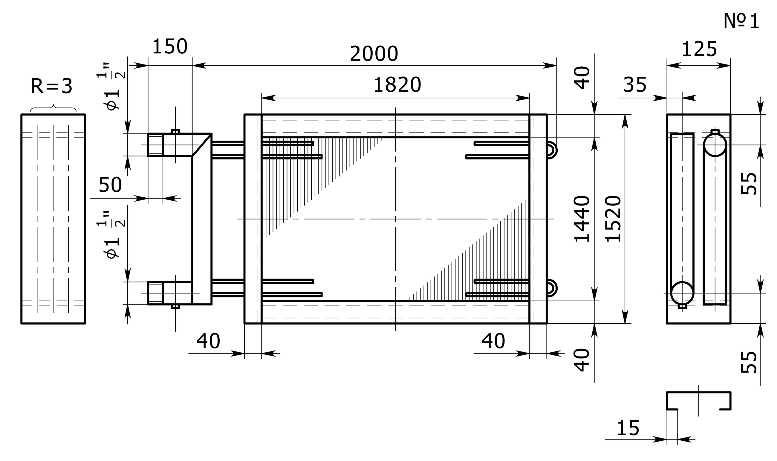
36 model cards: nine water coolers, nine refrigerant coolers and eighteen liquid-heater variants. Each has its own drawing and an existing UPGR model render.
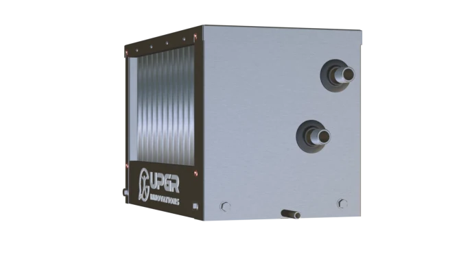
Nine sizes. For glycol mixtures, confirm material compatibility and recalculate duty and pressure drop.
9 models ↗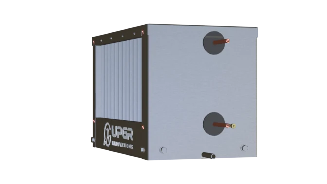
Nine sizes. Select the refrigerant, circuit arrangement and operating conditions separately.
9 models ↗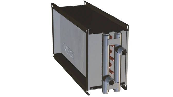
Nine sizes in two variants. Archived water ratings do not establish glycol performance.
18 variants ↗04 / CONSTRUCTION AND SUPPLY
A clear specification connects the required duty, material boundaries and acceptance criteria. Check these points before agreeing the construction.
Choose the duty first: air heating, liquid cooling, refrigerant evaporation or condensation. Then agree the mounting envelope, materials, circuits and connections for the selected equipment.
Confirm tube and fin materials, casing metal and protective coatings for the specified air and fluid. A copper–aluminium core does not define the casing material.
Agree the thermal calculation, drawing revision, pressure and leak tests, and the documents supplied with the coil. Record acceptance criteria in the specification.
Price, lead time and exact construction are confirmed against the enquiry.
05 / ENGINEERING RESOURCES
Use the UPGR measurement worksheet to record dimensions and save it as PDF from the print dialog. The selection form collects duty and fitting data for engineering review.
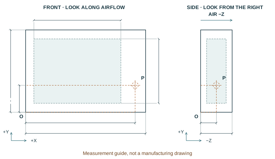
Front and side views, separate overall and finned dimensions, connection references and a photo checklist. Original UPGR schematic with blank measurement fields.
Open worksheet / save PDF ↗Measurement guide. Not a manufacturing drawing.See how tubes, fins, headers, return bends and the casing work together, and which components depend on the duty.
Explore the components ↗Start with the airflow, inlet and outlet conditions, working fluid and allowable pressure losses. Use the measurement sheet for replacement dimensions. These tools prepare the enquiry; they do not calculate a coil rating or price.
Selection checklist ↗Measurement sheet and PDF ↗| Operating condition | What to compare | What to confirm |
|---|---|---|
| Dust and cleaning | Fin spacing and service access | Cleaning method, filters, fouling and allowable pressure drop |
| Corrosive air or fluid | Tube/fin/casing material and protective coating | Exact medium, cleaning chemicals and written material compatibility |
| Condensation or frost | Drainage, fin spacing and defrost provision | Humidity, operating cycle, drainage orientation and access |
| Part-load control | Circuit arrangement and control stages | Refrigerant, system control and the manufacturer's circuit drawing |
These are selection questions, not universal material recommendations. Compare candidates at the same operating conditions.
06 / YOUR ENQUIRY
Your task, known parameters and files — in one enquiry. Enter the information you have; missing values can be left blank.
Operating duty and missing inputs, a selection sheet, an installation drawing, then price and lead time for the agreed construction.
Contact UPGR
info@upgradefor.com
A photo is useful for an initial enquiry, especially with a nameplate. It does not establish hidden circuiting, accurate dimensions or thermal performance. Those need additional data.
Photo and measurement checklistDimensions establish whether it fits. Performance also depends on the working fluid, temperatures, airflow, fin geometry and circuiting. Both installation and operating requirements need checking.
Duty and installation checklistNo. Compatibility with the fluid and the surrounding air must be checked. Corrosive exposure, cleaning chemicals or special hygiene requirements may call for a different material or a specified protective coating.
Conditions that change the constructionUntil duty and construction are known, a number would not describe your coil. A technical selection and an offer should refer to agreed inputs, quantities and delivery requirements.
Enquiry with the inputs you already know