Prepare a replacement enquiry using the nameplate, drawing or site measurements. Check the fit, connection orientation and operating duty before agreeing the replacement.
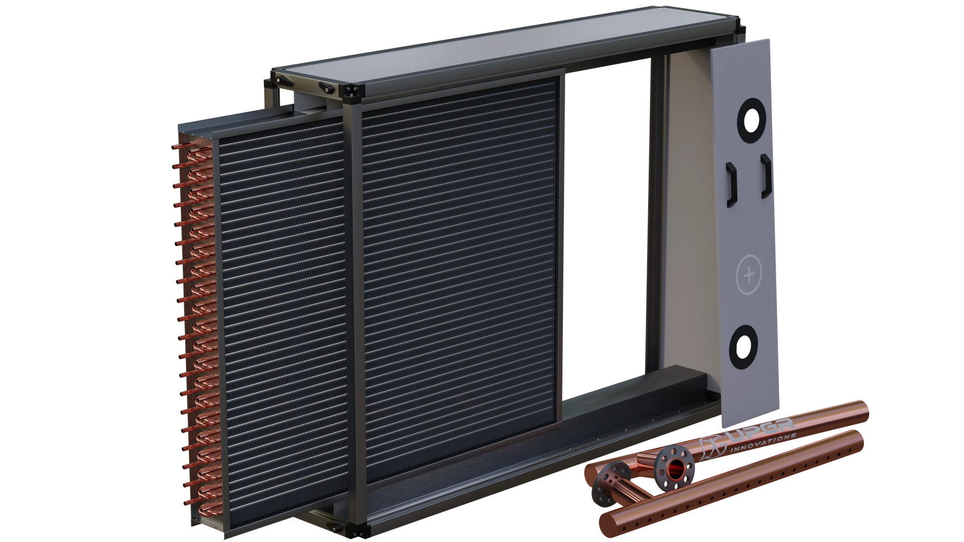
UPGR archive 3D disassembly view. It illustrates access and separate components, not a completed repair or verified replacement.
01
Identify the original product
Record the manufacturer, model and available markings without guessing unclear characters. An equipment overview establishes context; photographs of the coil and connections identify the replacement subject. If the specification and installed product differ, retain both sources and flag the discrepancy. It needs assessment rather than choosing whichever version is more convenient.
02
Measurements with a clear orientation
A measurement is useful when its reference points are clear. Distinguish the finned section from overall dimensions, the mounting frame and projecting connections. Identify airflow direction and the viewing position; left and right can otherwise be ambiguous. An annotated photograph helps align the descriptions, but does not replace a verified drawing.
03
Check operating conditions and replacement scope
Matching the mounting arrangement is only one part of the assessment. The coil function, working medium, available operating data and equipment constraints are also needed. Identify which components will remain, such as the frame, casing, fans, pipework or other assemblies. The preparation produces an agreed context for assessment, not confirmation of interchangeability or installation suitability.
FROM THE UPGR LIBRARY
Read a dimensioned coil drawing
These existing archive examples show how face dimensions, overall dimensions and connections are recorded. Dimensions belong to the illustrated examples; the drawing for your order is agreed separately.
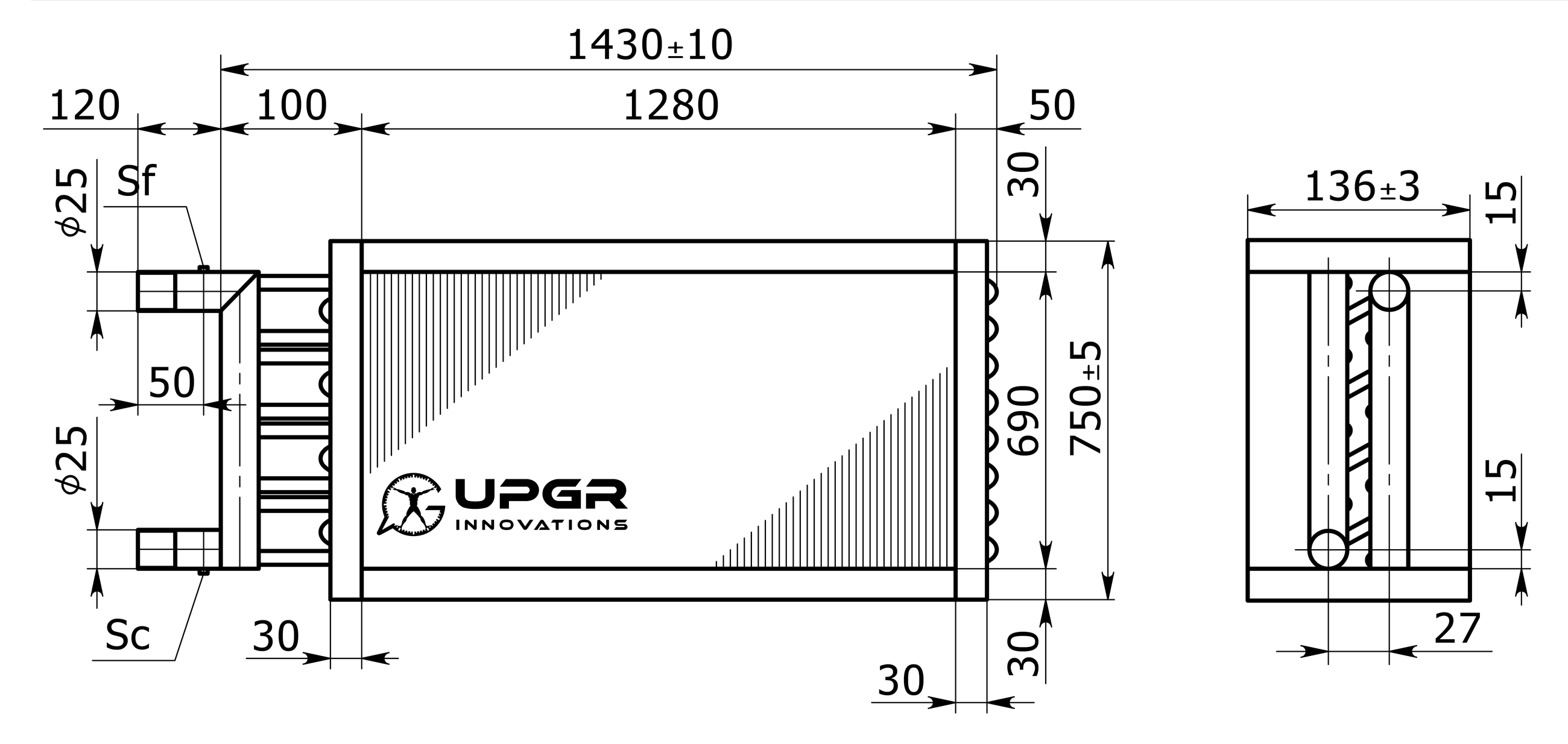
Two views and dimensional tolerances
UPGR archive, April 2022. Dimensioned sketch; scale and fabrication approval are not established. Open the image to read the details.
Finned face
The example states 1280 × 690 mm. This is not the full envelope with frame and projecting connections.
A nominal size includes its tolerance
750 ± 5 mm and 136 ± 3 mm are dimensions of this example. Check their extension lines and reference surfaces before comparing an opening.
Connections need more than a diameter
The drawing shows Ø25, but connection type, position, function and viewing direction must also be agreed. Do not derive missing coordinates by measuring pixels.
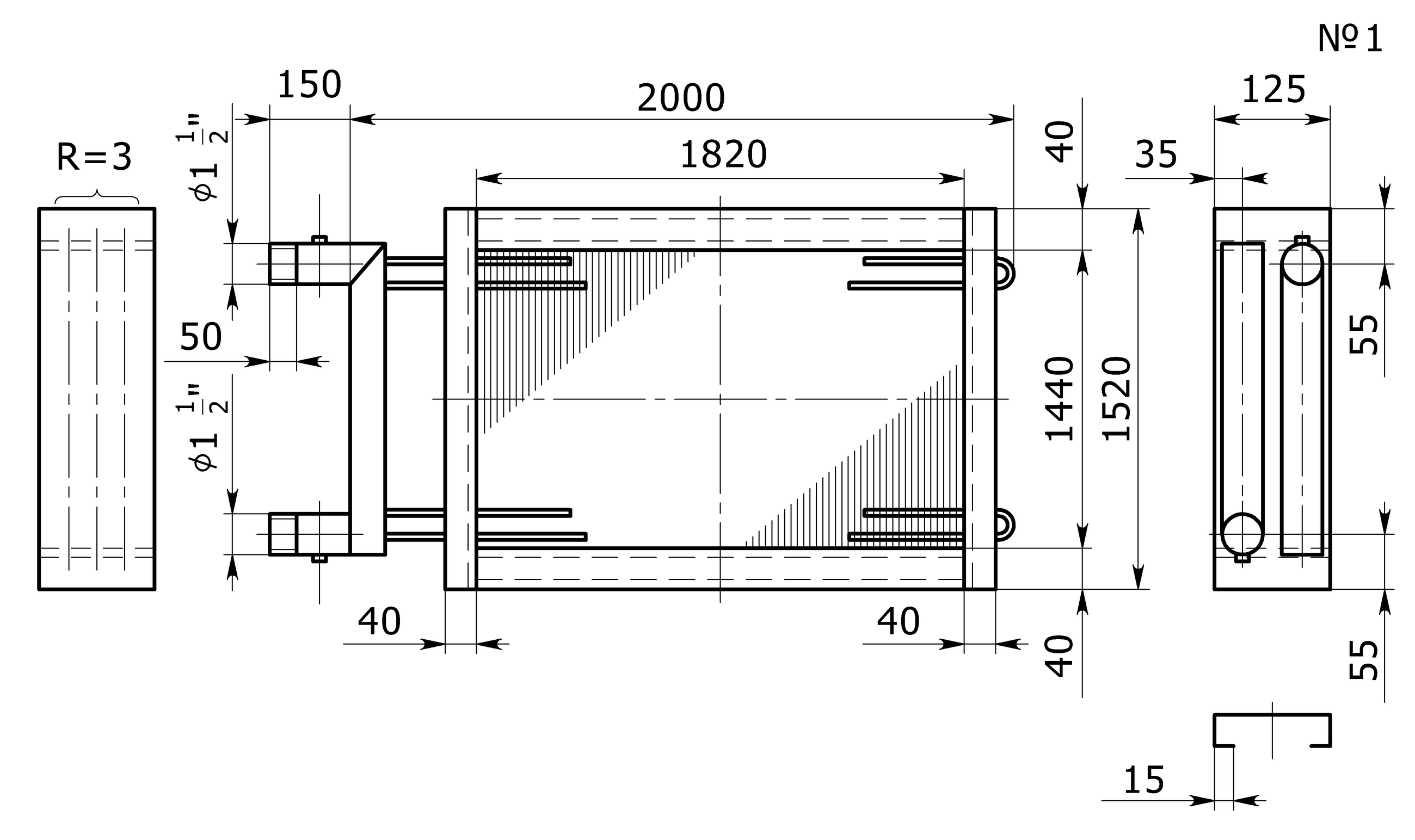
Another example: multiple views and a profileArchive sketch No. 1, October 2022. Schematic, not to scale. This is a separate example and is not another view of the first coil.
DRAWING AND SPECIFICATION
What an agreed drawing needs to show
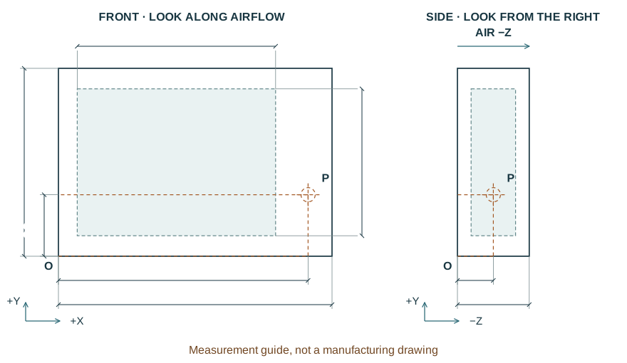
This educational schematic helps you read dimensions and prepare measurements. The manufacturer drawing must also identify the configuration, materials, tolerances and revision.
Actual measurements are blank. This schematic does not specify product dimensions or construction.
A · B · CComplete envelope
Full width, height and depth including projections. Check the opening and the path needed to remove the coil.
Wf · HfFinned face
Dimensions of the finned block only. Do not substitute the frame or AHU casing dimensions.
Xp · Yp · ZpConnection axes
Offsets from one stated datum. Each connection also needs its own position, diameter, connection type and function.
IdentityModel, drawing number, revision and approval status. A preliminary drawing does not authorize manufacture.
ConfigurationTube, fin and frame materials and thicknesses; rows, fin pitch, circuits, fixings and orientation. Unknown items remain open questions.
Duty and verificationA selection sheet using the same operating conditions, permitted deviations, agreed tests and the required acceptance documents.
Modine DX Coils, page 3, Figure 6: dimensional enquiry data. Aerofin General Products Catalog, printed page 3: orientation and ordering information. These illustrate document content, not the specifications of the offered product.
Identify airflow direction and viewing side on every view. Reference connections and fixings to consistent datums; left and right without a stated view cannot rule out a mirrored arrangement.
Fit and access
Compare the overall envelope, finned face, projecting connections and fixing holes. Include the access opening and removal path, and distinguish measured dimensions, documented values and unresolved dimensions in the review.
Duty and agreed replacement
Provide the working fluid, known duty and reason for replacement. Before ordering, compare the proposed drawing and selection data with the original assembly; make the matches, deviations and retained components explicit.
SELECTION INPUTS
Inputs to prepare
Nameplates and available documentation for the equipment and coil.
Overview, finned surface, connections and installed position.
Drawing or measurements with reference points and airflow direction.
Function, working medium and known operating conditions.
Reason for the enquiry and the intended replacement outcome.
Replacement assembly boundaries and components that will remain.
What do you need to do?
Select a new coil
Define operating conditions first. The input checklist above describes the data needed for this application. The enquiry form adapts to the selected duty; it does not calculate a coil rating.
Add the equipment nameplate, photographs, overall and finned dimensions, airflow direction, connections and access constraints. Matching the envelope alone does not confirm performance or compatibility.
Separate fixed interfaces from dimensions open to change. Attach the current drawing revision, duty points, material requirements, quantity and acceptance criteria. Manufacturing feasibility is confirmed for the specific specification.
Final performance, materials and compatibility require a project-specific selection and an approved drawing.
Questions about this application
Can an enquiry start without a complete drawing?
Yes. Available photographs and markings can start identification. Missing information is recorded separately; beginning an enquiry does not mean there is already enough evidence to confirm a replacement.
Do identical overall dimensions guarantee compatibility?
No. Connections, construction, working medium and operating conditions also matter. Overall dimensions establish only part of the installation geometry and do not replace a combined technical assessment.
Must a replacement be an original OEM part?
State any requirement for the part's origin in the enquiry. An original part, manufacture to documentation and another replacement option are distinct proposals; similar appearance does not confirm any of them.