Heat exchangers
A heat exchanger transfers energy from a hotter medium to a colder one. Its construction, materials, working fluids and application describe different properties. Use this guide to distinguish the main families and find the right selection or replacement information.
All topics on this page
Tools and their limits
Choose an available tool for the next step. Catalogue filtering does not establish thermal performance or suitability.
- Standard coil sizes: filters and model cards
Compare catalogue dimensions and inspect individual model cards. Thermal selection requires separate verification.
- Thermal balance of two single-phase streams
Calculate the powers from mass flow, cp and temperatures, then compare both sides. The result does not select an exchanger or establish its dimensions.
- Standard coil drawings and dimensions
Read existing reference drawings and model dimensions. These are catalogue documents; the thermal-balance tool does not generate geometry.
Thermal balance: two single-phase streams
Calculate the heat released and absorbed from mass flow, specific heat capacity and inlet/outlet temperatures. Compare the two sides before preparing input data for equipment selection.
This is an energy-balance check, not a calculation of exchanger size or proof that an operating point is feasible. Boiling, condensation, air dehumidification and other phase changes are outside this method.
Method and example
Q = ṁ × cp × ΔT. With ṁ in kg/s and cp in kJ/(kg·K), Q is in kW. Hot side: Tin − Tout; cold side: Tout − Tin. Relative mismatch is |Qhot − Qcold| / max(|Qhot|, |Qcold|) × 100%. It is undefined when both powers are zero.
Steady operation with approximately constant cp on each side. Enter cp for the actual fluid, concentration and operating temperature; it is not looked up automatically. Heat loss, measurement uncertainty and transient effects can explain a mismatch. Zero mismatch alone does not verify phase state, temperature approach, heat-transfer area, pressure drop or suitability.
Illustrative input: 2 kg/s and cp = 4.18 kJ/(kg·K) on each side, hot 80 → 60 °C and cold 20 → 40 °C. Each side gives 167.2 kW, with 0% mismatch. These example properties are assumptions, not a fluid-property lookup or model selection.
Browser storage is unavailable. Inputs remain available in this tab, but cannot be retained when you leave.
Calculated balance
- Heat released, kW
- Heat absorbed, kW
- Released minus absorbed, kW
- Relative mismatch, %
Calculated from your entered values. Equipment feasibility and model suitability have not been assessed.
The brief stays in this browser until you download it. Nothing is sent; no price, stock or order is confirmed.
How heat transfer works
In a surface heat exchanger the media are separated by a wall. A regenerator stores and releases heat cyclically; in direct-contact exchange the media interact directly. Flow may be parallel, counter-current or cross-flow, and evaporation or condensation changes how duty is calculated.
Constructions
Back to contentsPlate
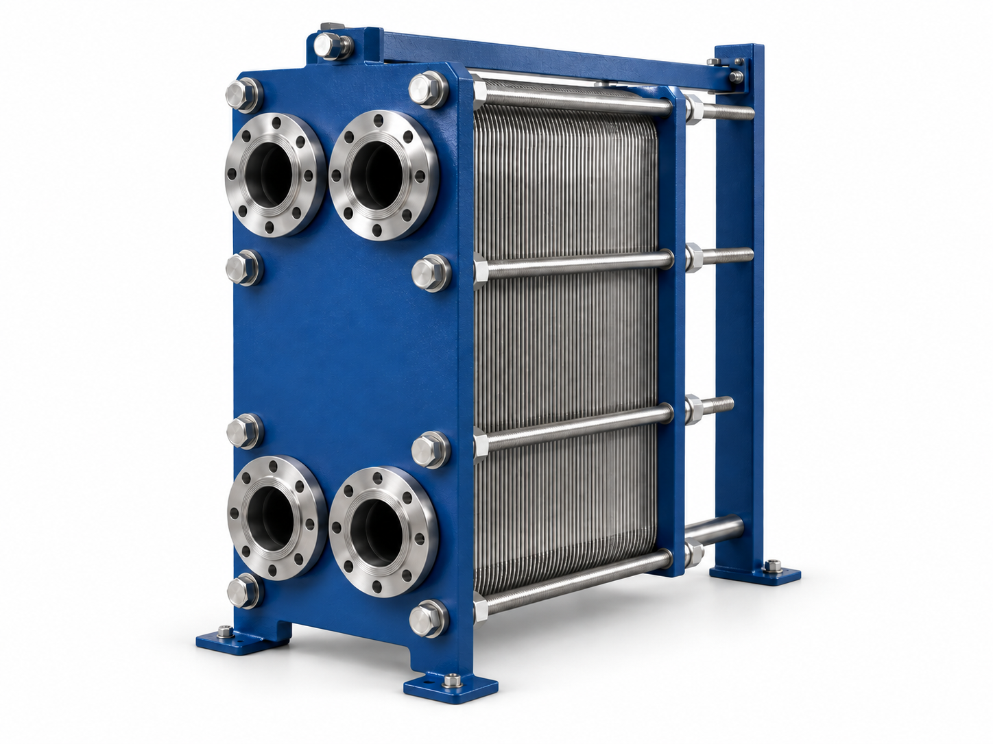
A pack of plates separates the fluid channels. Gaskets, brazing or welding determine how the pack is sealed and serviced; plate-and-shell and diffusion-bonded designs address other process requirements.
Shell and tube
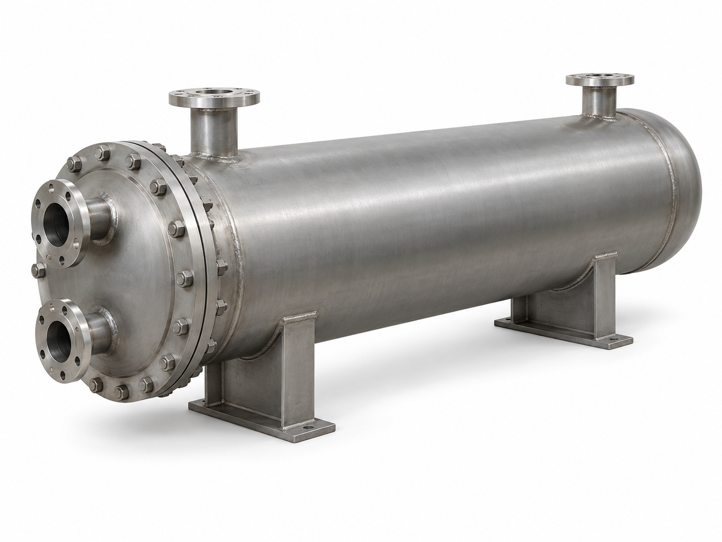
One medium flows through a tube bundle, the other around the tubes inside a shell. The tube-side and shell-side conditions are specified separately.
Finned tube
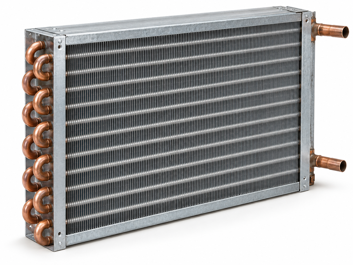
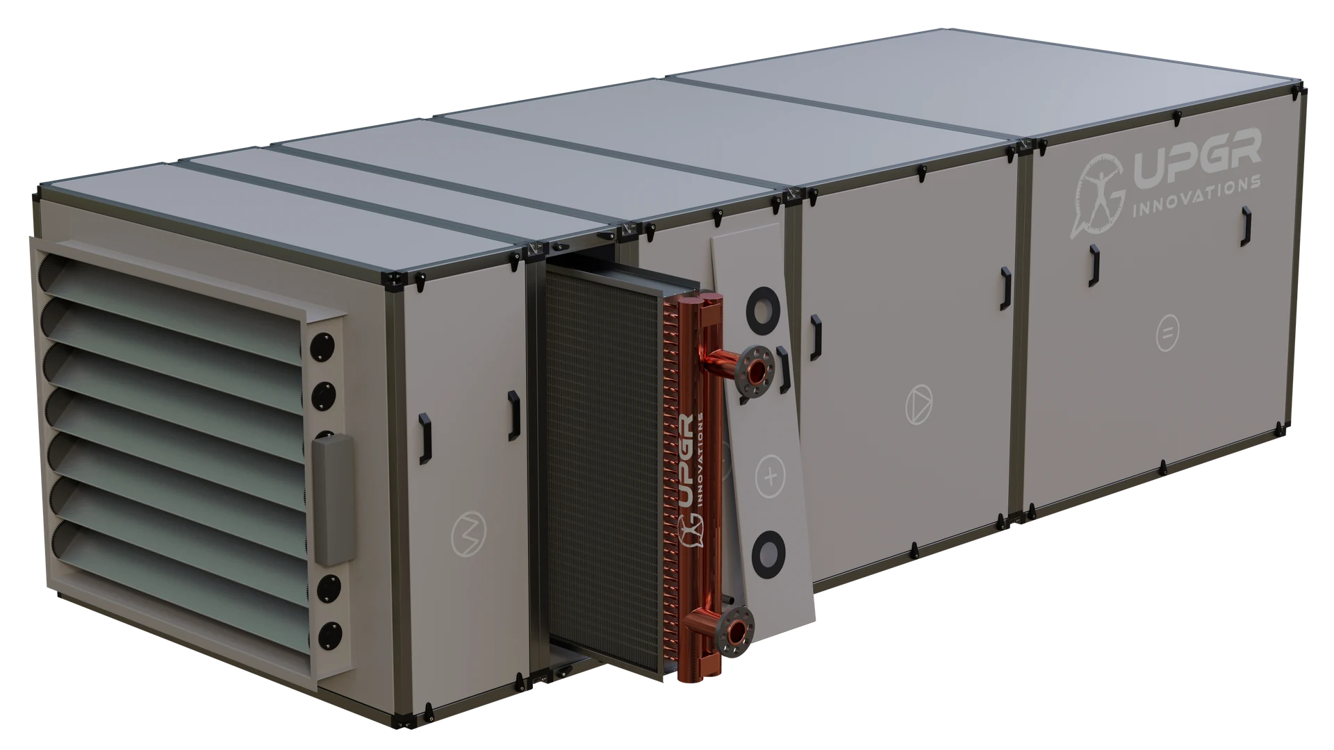
Fins increase the surface exposed to air. The tubes, headers, fins and frame form a coil; tube and fin materials may differ.
Tube in tube
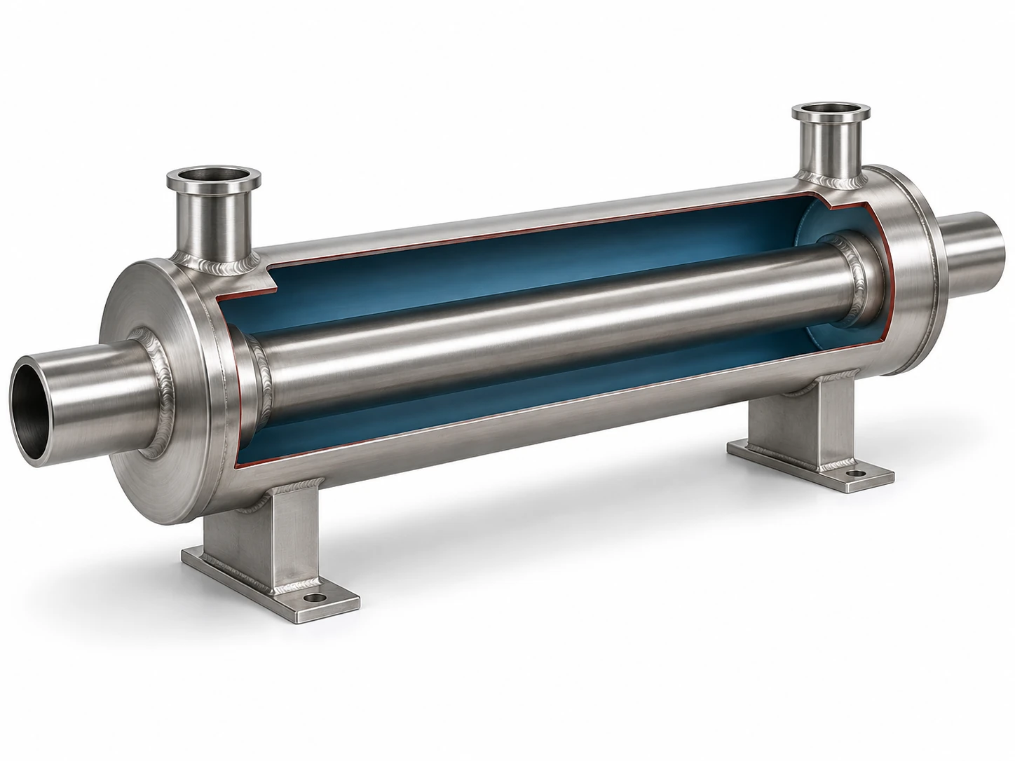
One fluid flows through the inner tube and the other through the space around it. This tubular construction is distinct from a bundle of tubes in a shell.
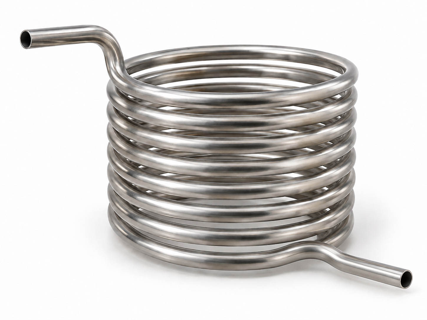
Coiled tube
A tube is formed into a coil and exchanges heat with the surrounding medium. A coil in a tank and a shell-and-coil unit differ in installation and access for cleaning.
Spiral
Metal sheets form spiral flow passages. Selection considers the media, fouling and the access provided by the specific design.
Microchannel
A flat tube contains many small passages connected to headers. All-aluminium microchannel coils are used in air-side heat exchange; they are not interchangeable with round-tube coils by dimensions alone.
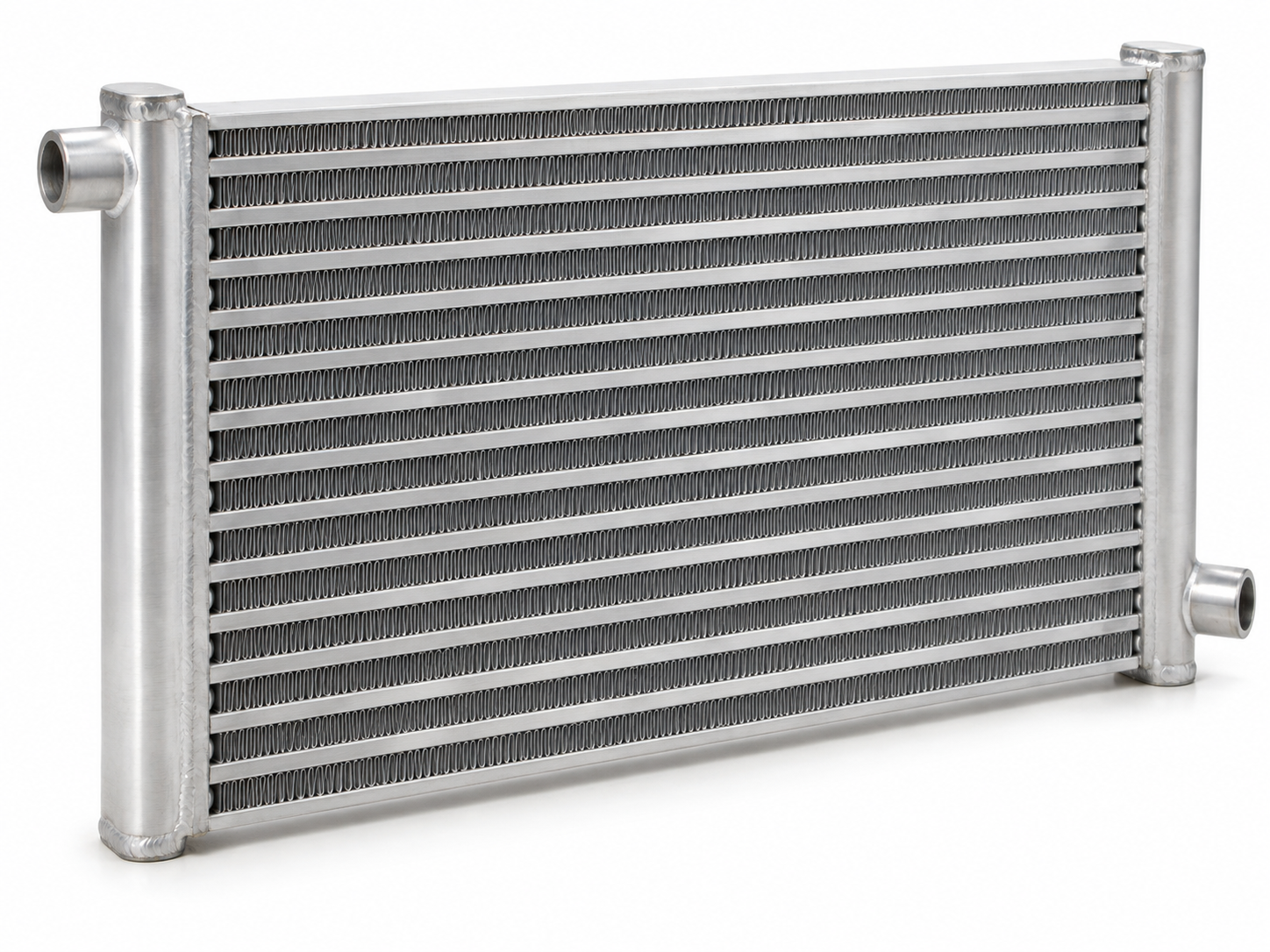
Plate-fin
Finned layers separate flow passages in a compact core. This family includes brazed aluminium exchangers used in cryogenic processes; it is different from a gasketed plate pack.
Scraped surface
Moving scrapers remove deposits from the heat-transfer surface during operation. These exchangers are used for viscous or sticky process products.
Materials
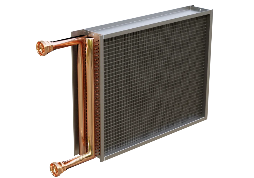
Back to contentsCopper–aluminium
Copper tubes carry the working fluid; aluminium fins provide the air-side heat-transfer surface. These finned coils heat or cool air in ventilation and refrigeration equipment.
Aluminium
All-aluminium designs include microchannel air coils. They differ from copper-tube coils with aluminium fins in their fluid passages and construction.
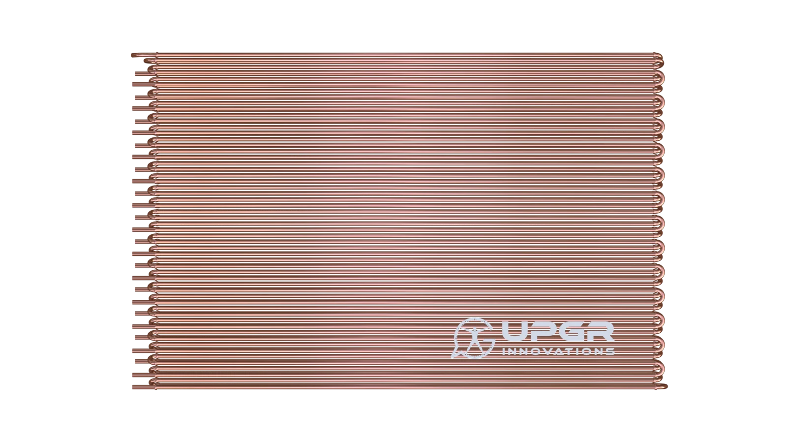
Copper
Specify whether copper is used for tubes, fins or both. A copper tube with aluminium fins is a copper–aluminium coil, not an all-copper heat exchanger.
Carbon steel
Steel may be used in tubes, a shell or structural parts. The grade and corrosion conditions matter; the material of an outer frame does not identify the heat-transfer surface.
Stainless steel
Stainless steel can be used for heat-transfer plates, tubes or a casing. The material is specified for each part in contact with the medium; a stainless casing does not define the internal circuit.
Titanium
Titanium plates are used in some seawater cooling duties. Material selection still depends on the full medium composition and operating conditions.
Working fluids
Back to contentsWater
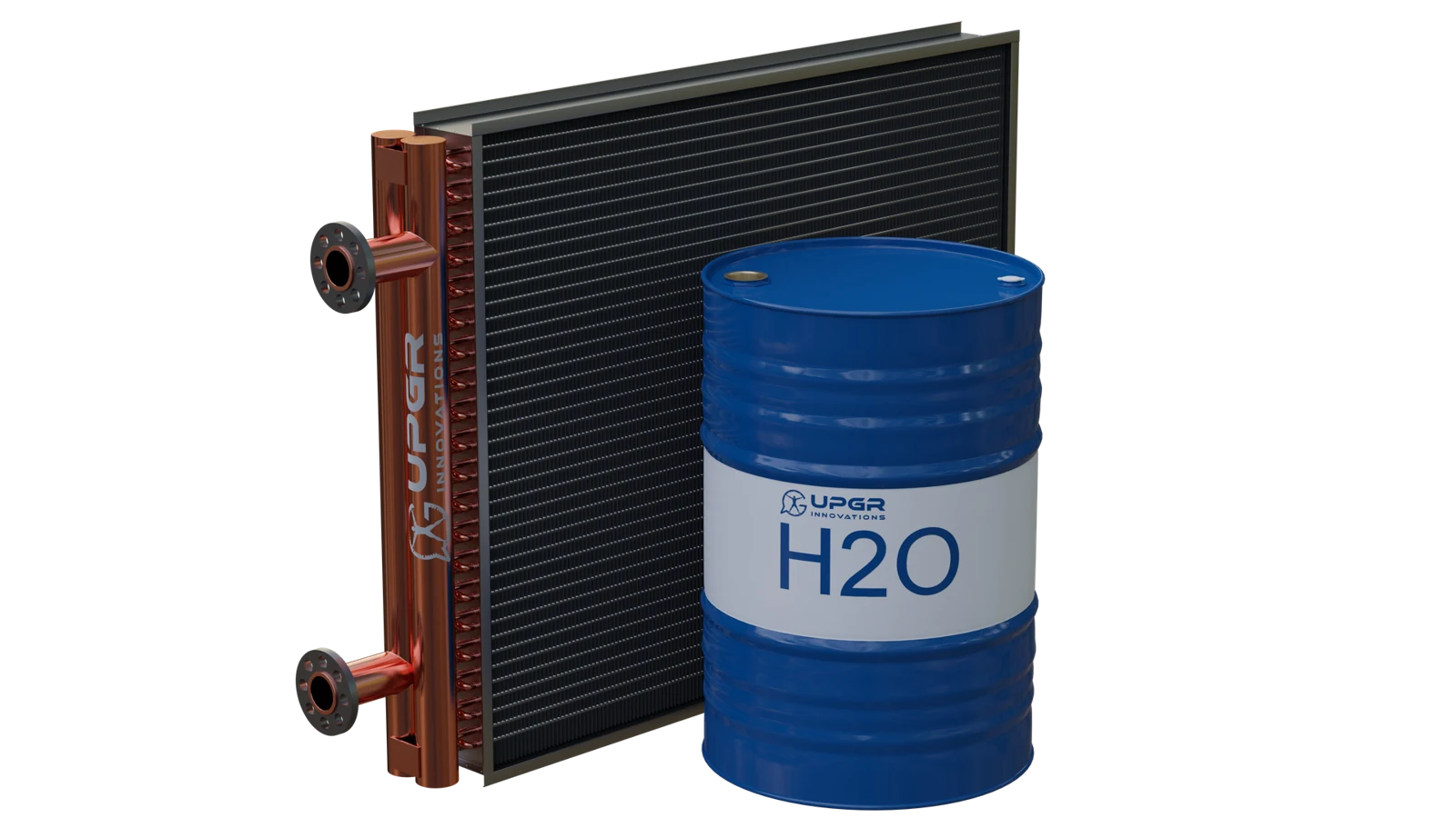
Water can heat or cool air in a finned coil, or exchange heat with another fluid in a plate or tubular exchanger. The task determines the construction.
Glycol
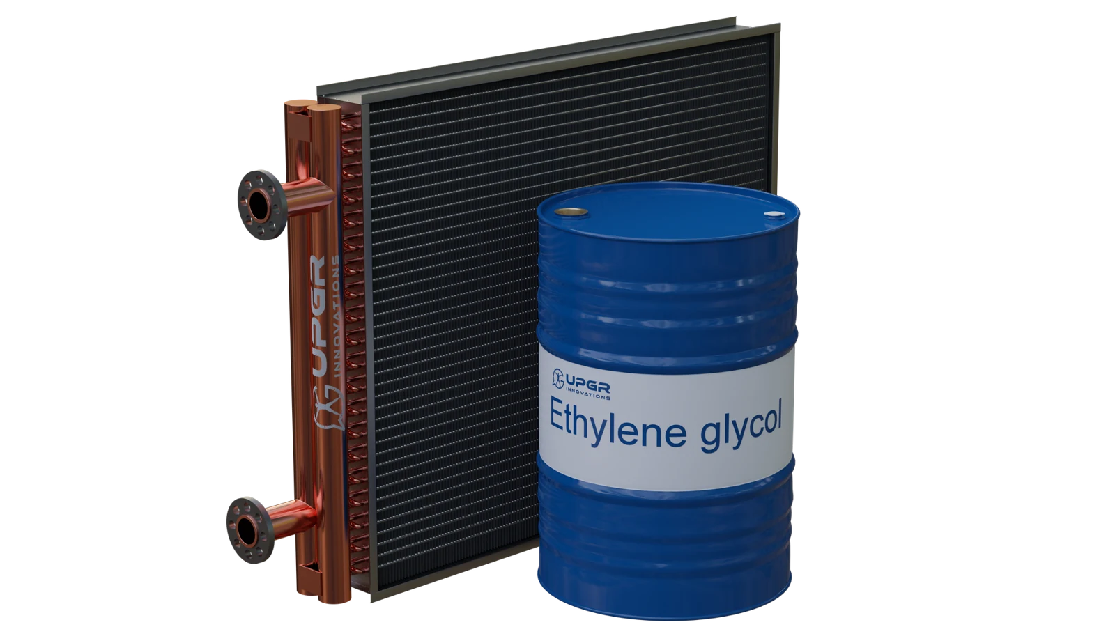
These exchangers use ethylene- or propylene-glycol solutions. Type, concentration and temperature affect heat transfer, pressure drop and freeze protection; a fluid name alone is not enough for selection.
Refrigerant
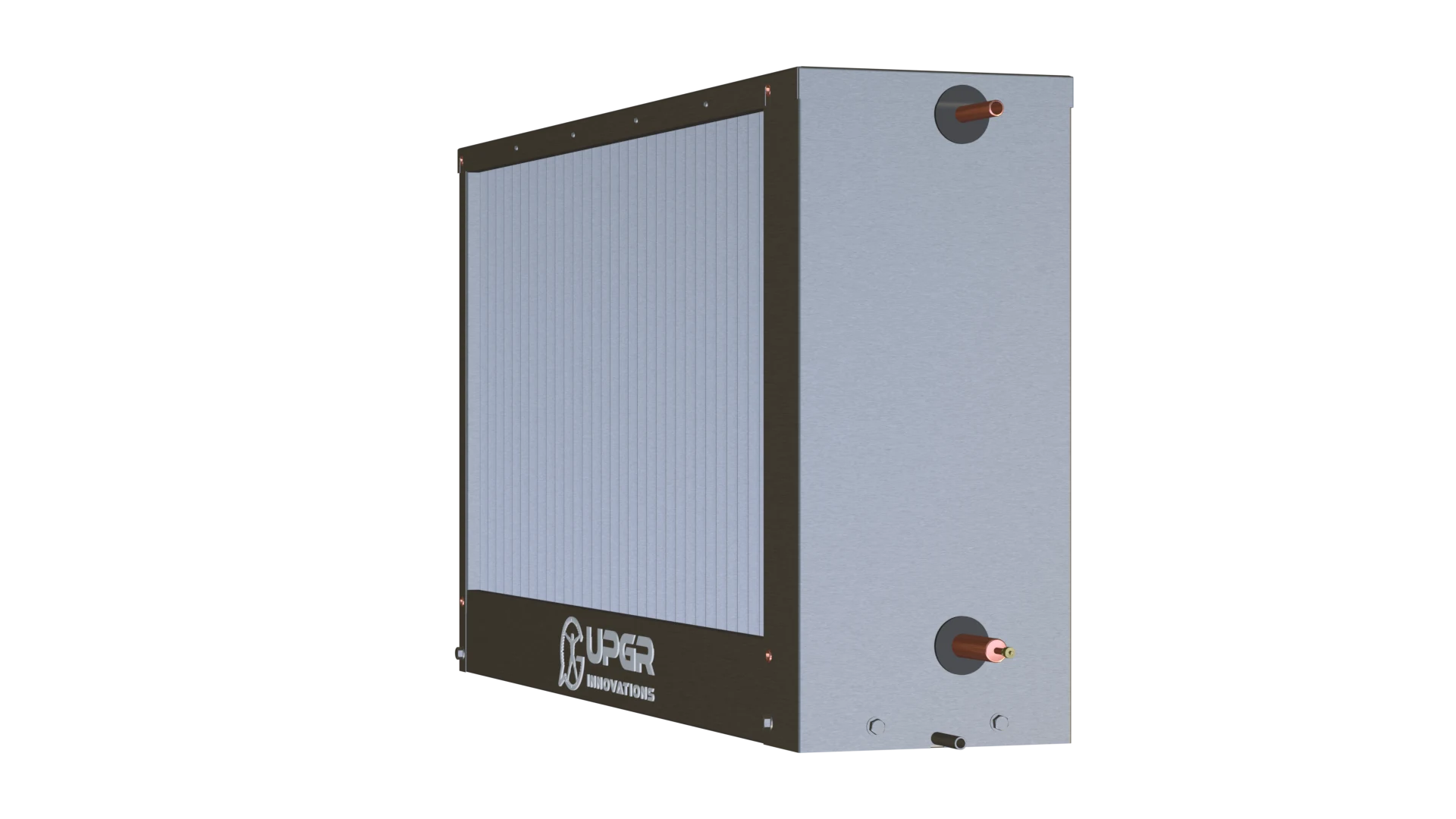
Refrigerant absorbs heat in an evaporator and rejects heat in a condenser. The cooled or heated medium may be air or liquid; the exact refrigerant and operating conditions define the requirements.
Steam
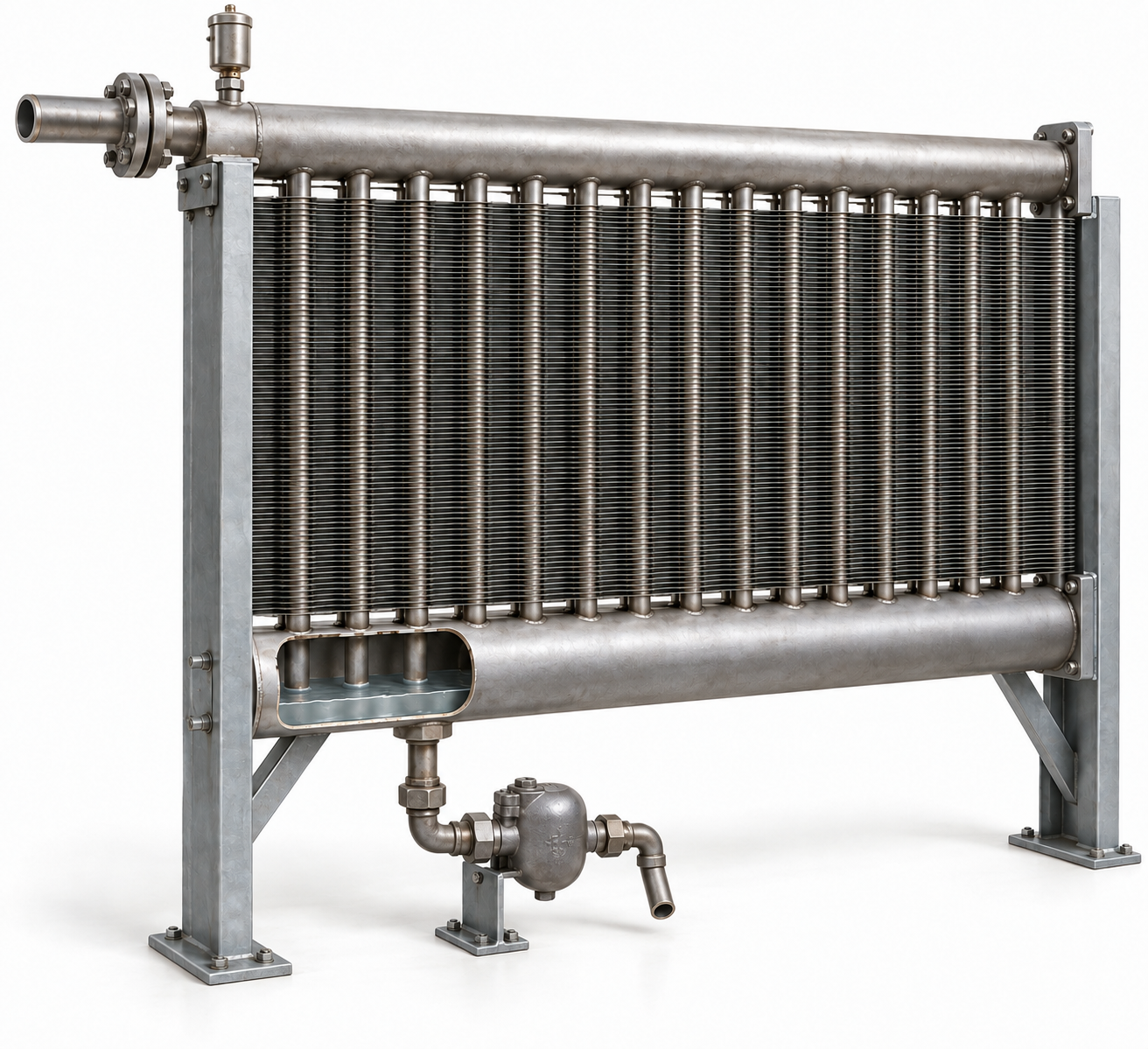
Condensing steam can heat water, air or a process fluid. Steam pressure, required duty and condensate removal must be considered together.
Oil
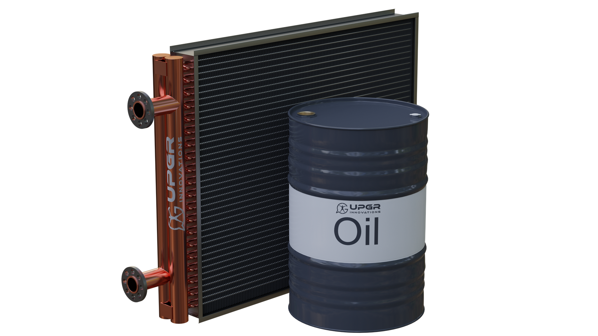
An oil cooler transfers heat from oil to air or another fluid. State the oil grade and viscosity at operating temperatures, as well as the flow and allowable pressure drop.
Air and gases
Air may exchange heat with a liquid, a refrigerant or another air stream. “Air heat exchanger” therefore describes a medium, not one universal construction.
Process fluids
Brines, process liquids and viscous products require a stated composition and contamination level. Materials, passage geometry and cleaning access are chosen for that medium.
Heat-transfer duties
Back to contentsHeaters and air heaters
A heater raises the temperature of a liquid, gas or process product. An air heater, also called a calorifier in Russian HVAC usage, heats an air stream; selection requires the conditions on both sides.
Coolers and air coolers
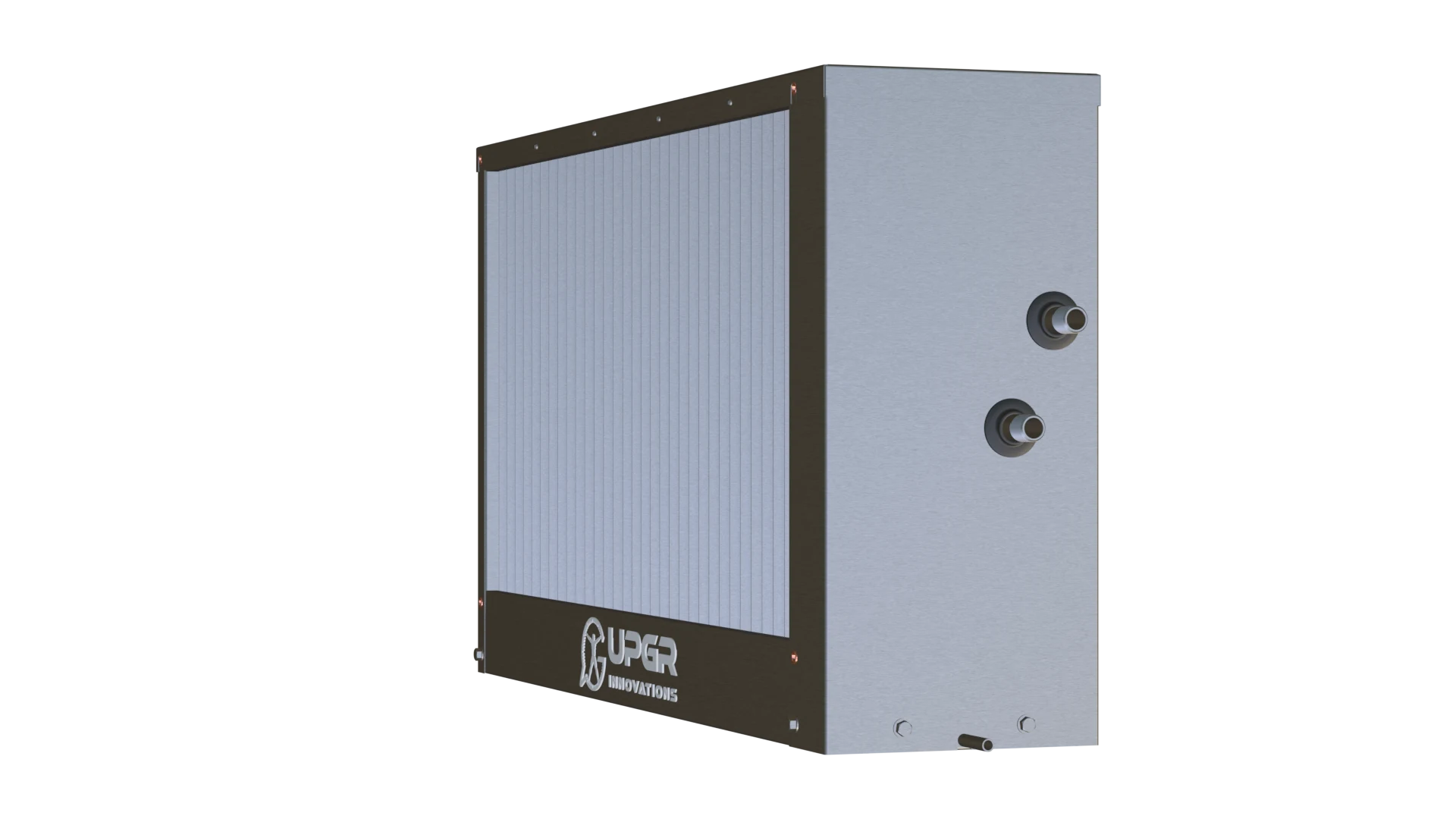
A cooler removes heat from a liquid, gas or product. An air cooler treats an air stream; if moisture also condenses, selection includes humidity, a condensate tray and drainage.
Evaporators
A liquid evaporates by absorbing heat. Refrigeration evaporators boil refrigerant to cool air or liquid; process evaporators may instead evaporate water or another process medium.
Condensers
Vapour condenses into liquid while releasing heat. This may be refrigerant in a refrigeration system or steam in a process; the cooling side can use air or a liquid.
Heat recovery
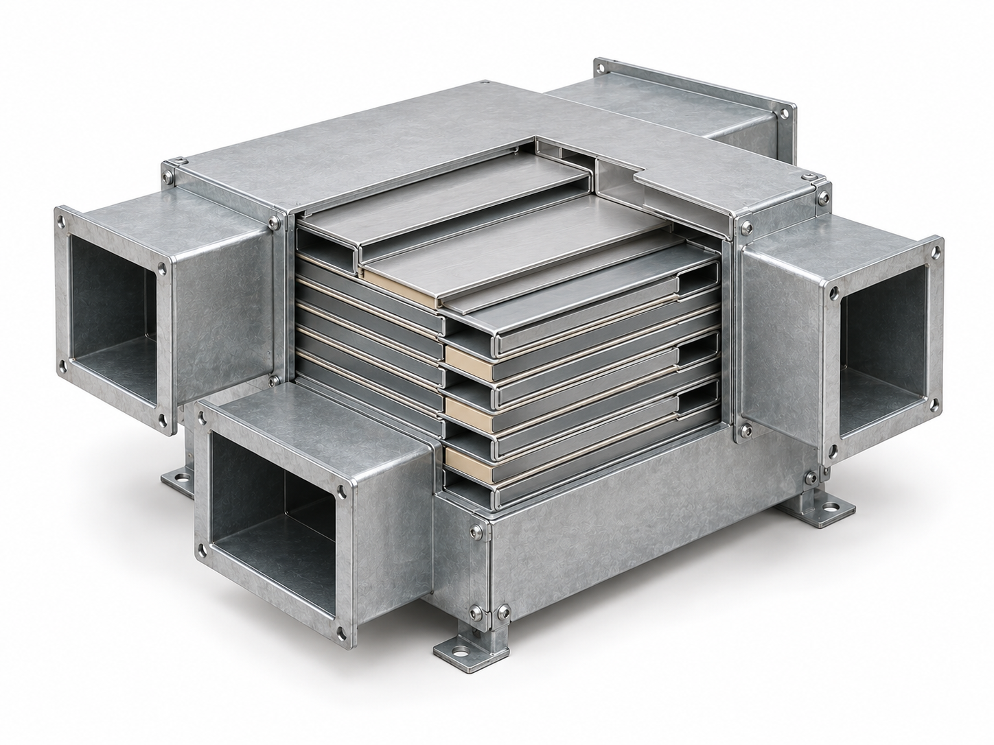
Ventilation heat recovery may use plates, a rotary regenerator, heat pipes or two coils connected by a liquid loop. These arrangements differ in how energy is transferred and in possible carry-over between air streams.
Equipment and applications
Back to contentsFor air handling units
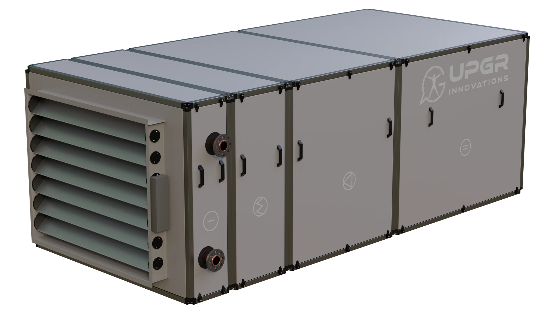
Supply and supply-and-exhaust units can contain heating, cooling and heat-recovery sections. A coil is one component of the unit: check the airflow, working fluid, installation envelope and access for service.
For chillers
A chiller contains exchangers with different roles: its evaporator cools liquid, while its condenser rejects heat. Some units also have a free-cooling coil. Identify the particular component before specifying a replacement.
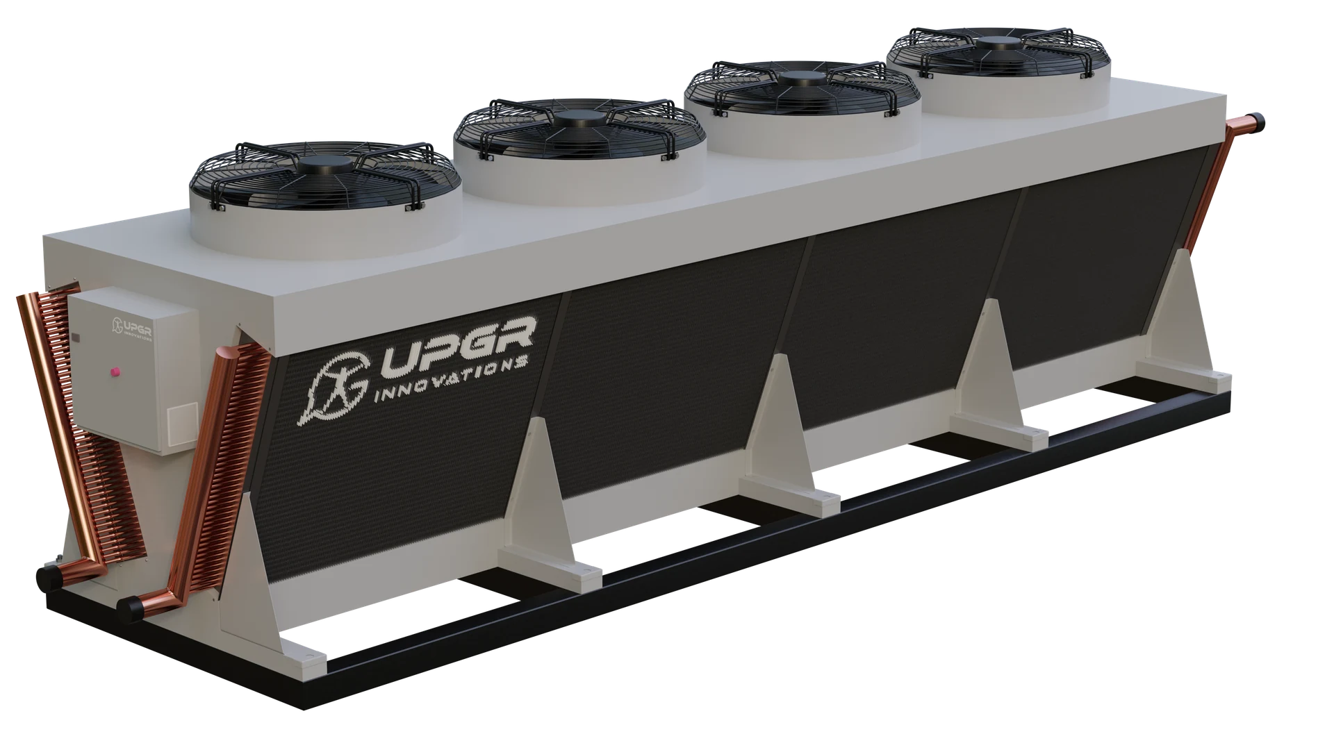
For air conditioners
Identify the air-conditioner type, operating mode and exact exchanger. Comfort and precision equipment may use different cooling arrangements. A replacement enquiry must identify the refrigerant or water circuit as well as the unit and coil.
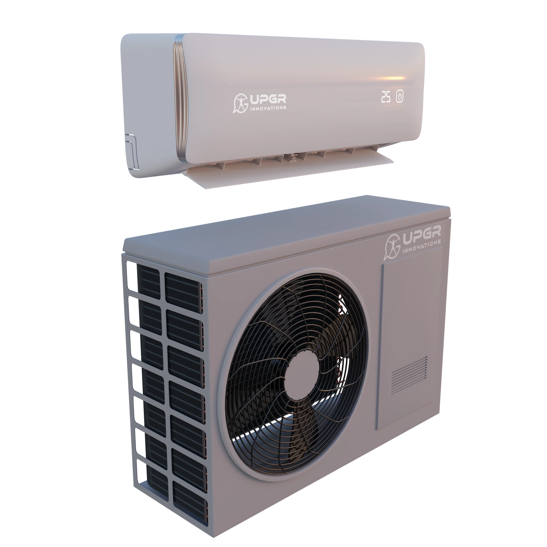
Precision air conditioners and server-room cooling
Precision cooling includes direct-expansion and chilled-water arrangements. A water cooling coil, a refrigerant evaporator and a condenser have different circuit roles; “precision” describes the equipment application, not one exchanger construction.
Provide the exact model, cooling arrangement, component position and circuit diagram. Confirm the working fluid, operating temperatures, airflow and connections before comparing replacements. Do not infer compatibility from a split-system resemblance or the CRAC/CRAH abbreviation alone.
For split systems
A split system has heat exchangers in separate indoor and outdoor units. Selection for replacement requires the model, refrigerant, connections and circuit arrangement.
For multi-split and VRF systems
Several indoor units operate with a shared outdoor system. Multi-split and VRF/VRV equipment must be identified by the exact series; similar appearance does not establish coil compatibility.
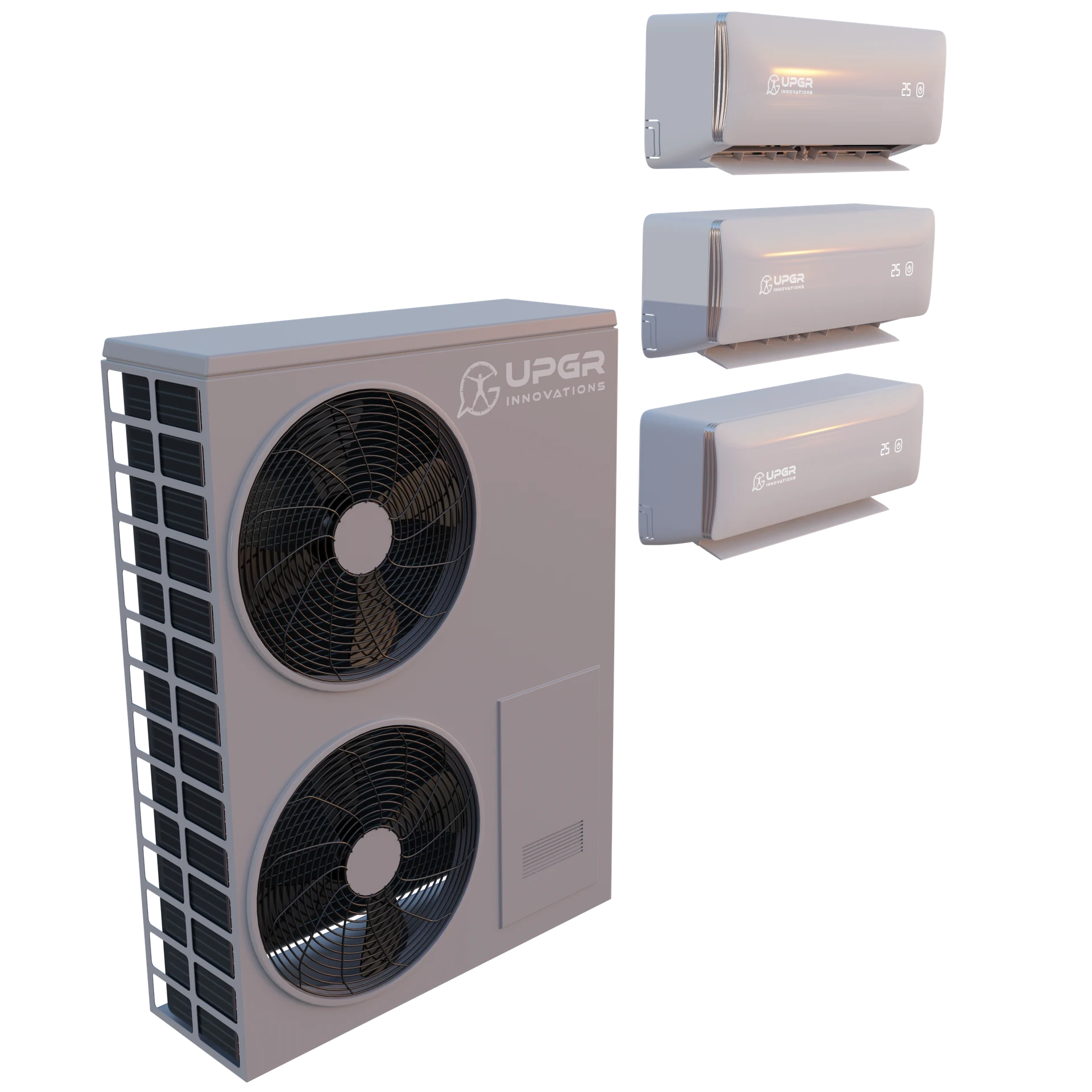
For rooftop units
A rooftop unit combines air handling and cooling or heating functions in one cabinet. Identify the required section and access for removal before specifying a replacement.
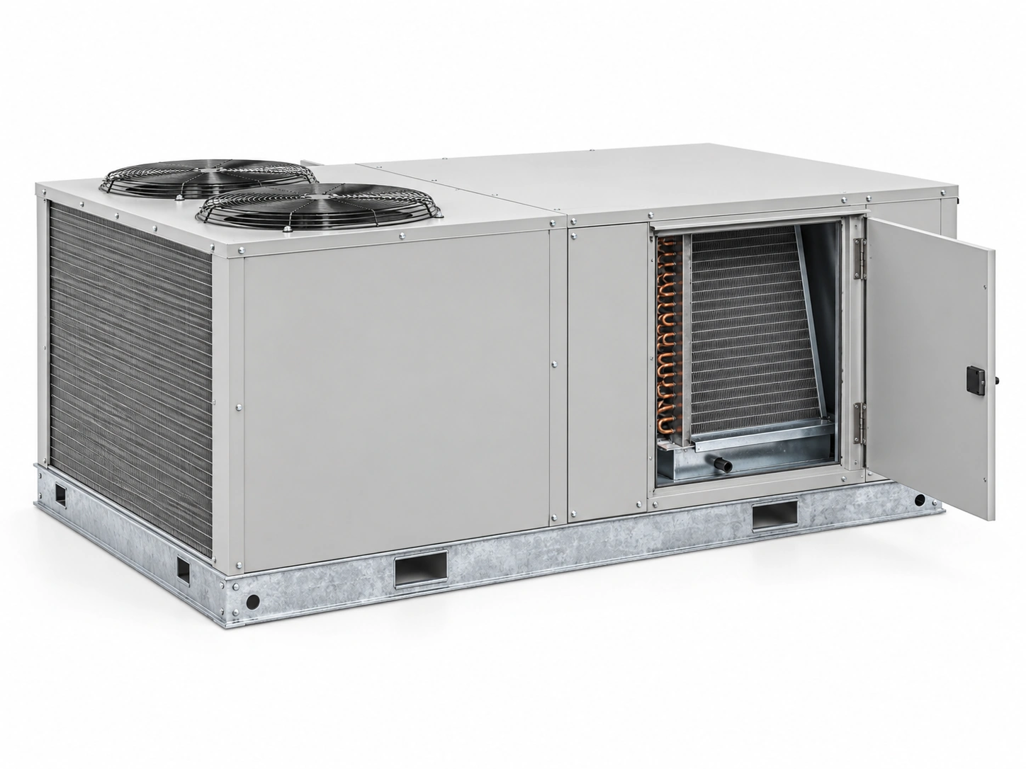
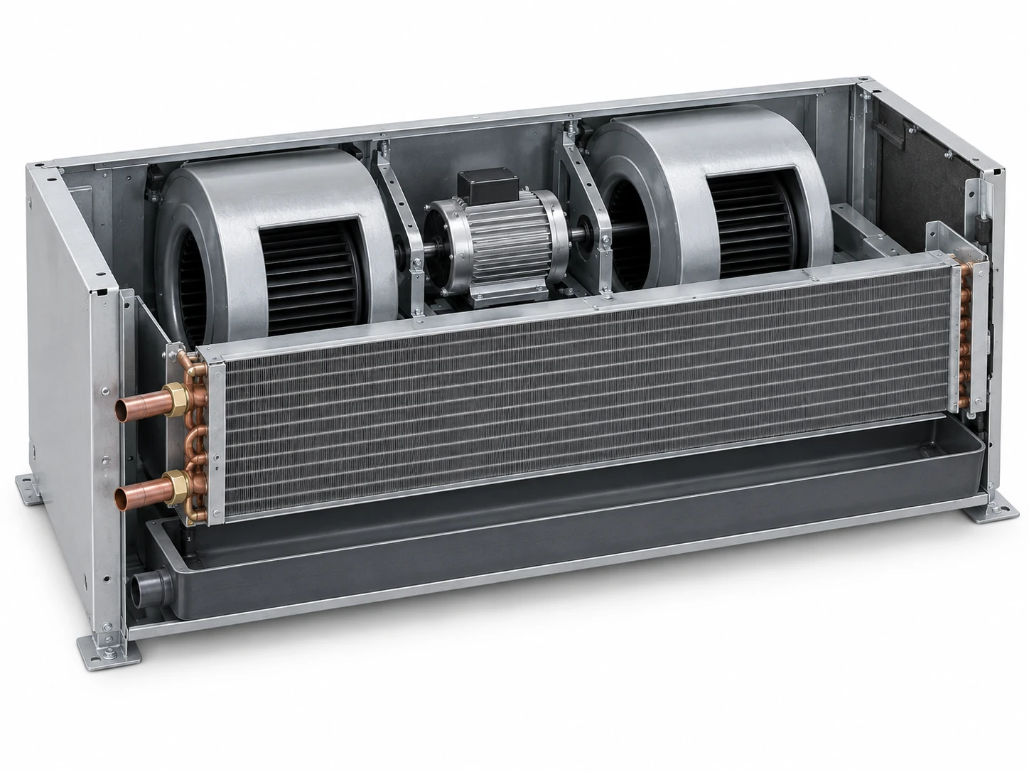
For fan coils
A fan blows room air across a water coil. For replacement, check the water circuit, rows, finned dimensions, connections and condensate tray arrangement.
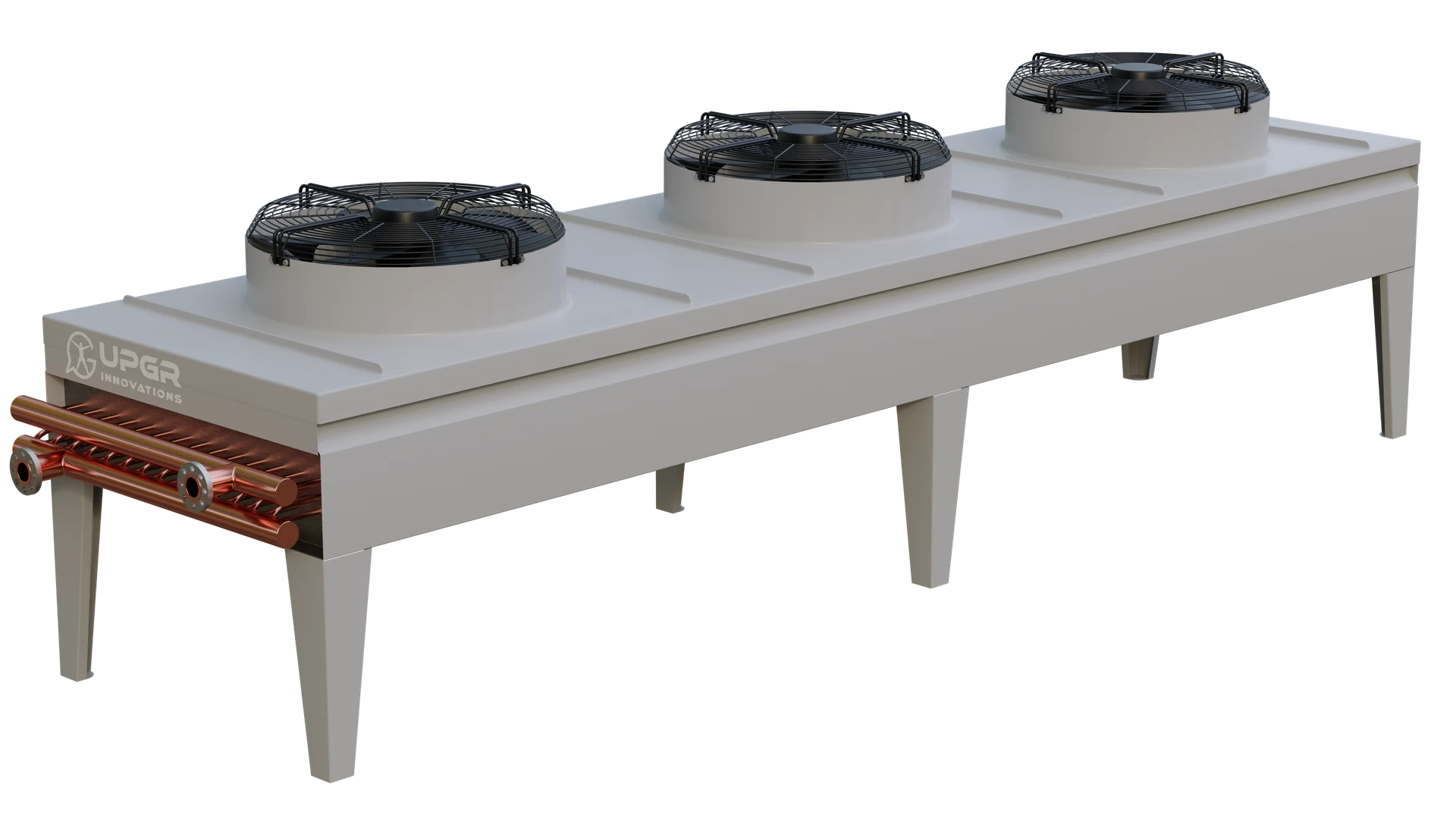
For dry coolers and cooling towers
A dry cooler rejects heat from a liquid through a coil to outdoor air. Evaporative cooling towers use a different heat-rejection process; a dry-cooler coil must not be assumed to fit every tower.
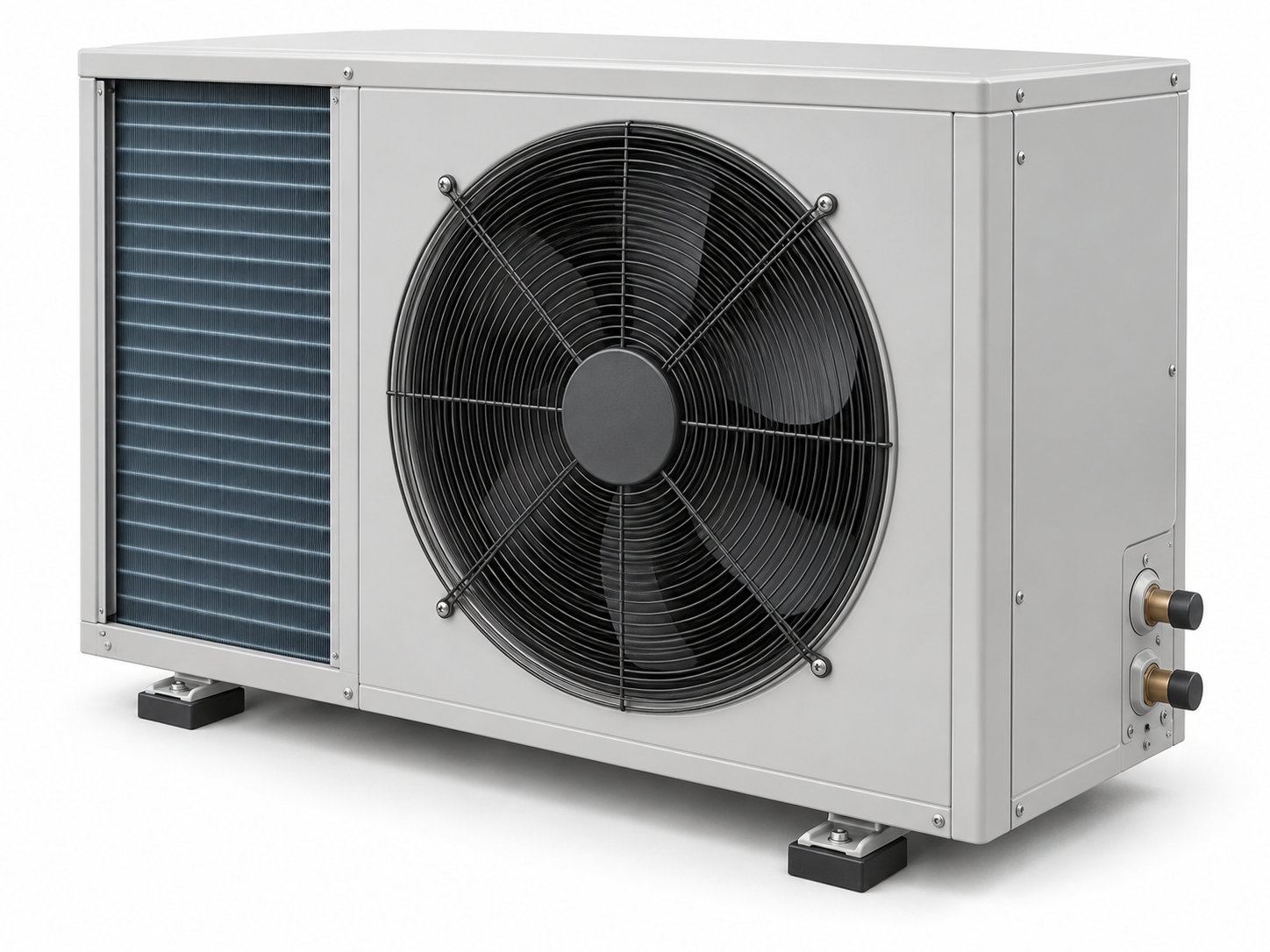
For heat pumps
A heat pump transfers energy between its source and heating circuit through an evaporator and a condenser. Air, water or ground loops require different exchanger arrangements and operating checks.
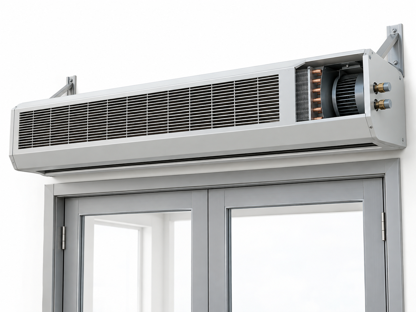
For air curtains and fan heaters
Water-fed models use a coil to heat an air stream. Identify the heater type first: equipment with an electric heating element does not have a water heat exchanger to replace.
For cold rooms
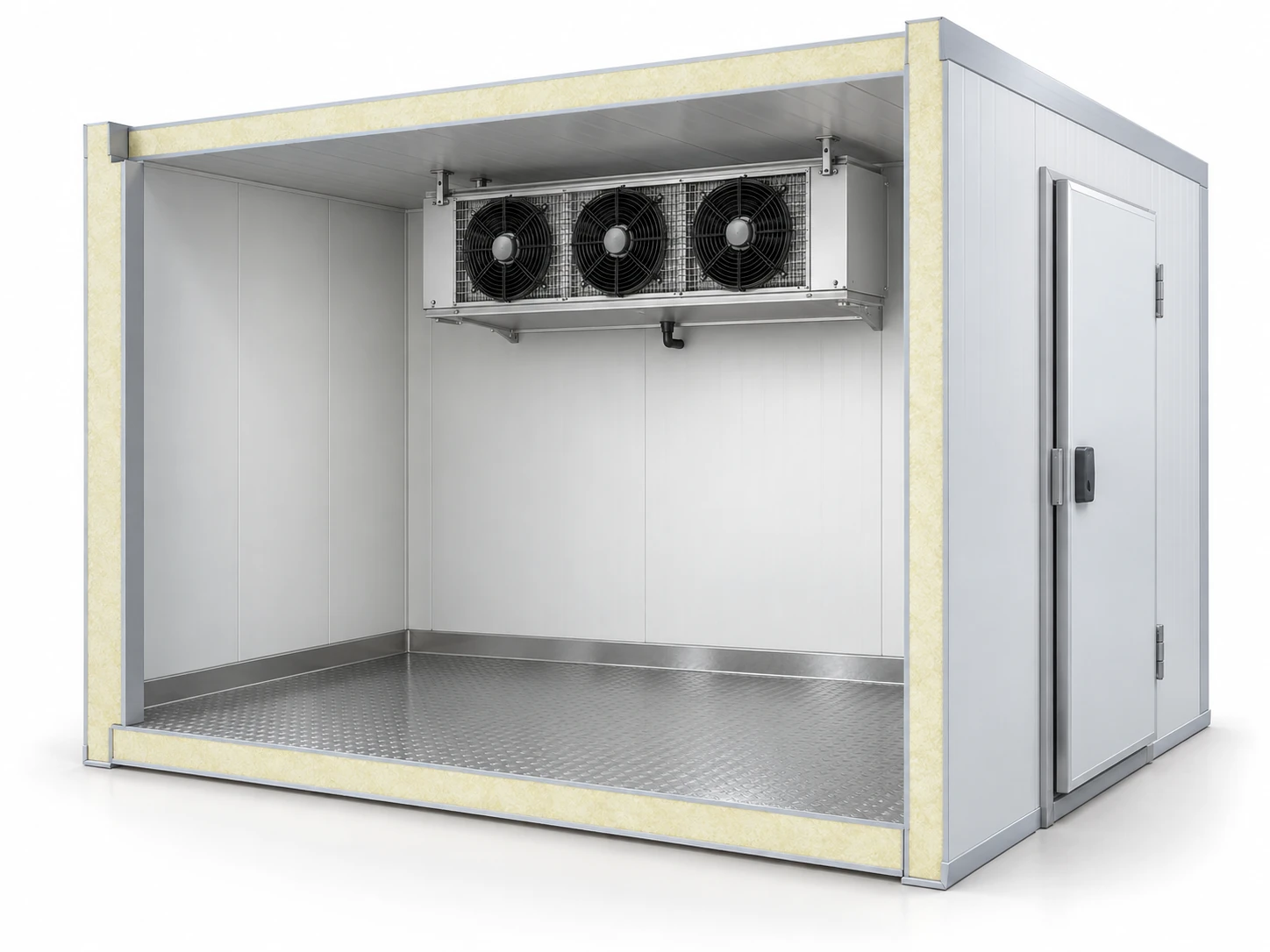
An air cooler removes heat from the chamber. Selection includes room conditions, airflow and defrost arrangements; the air-cooler assembly includes more than the coil itself.
For condensing units
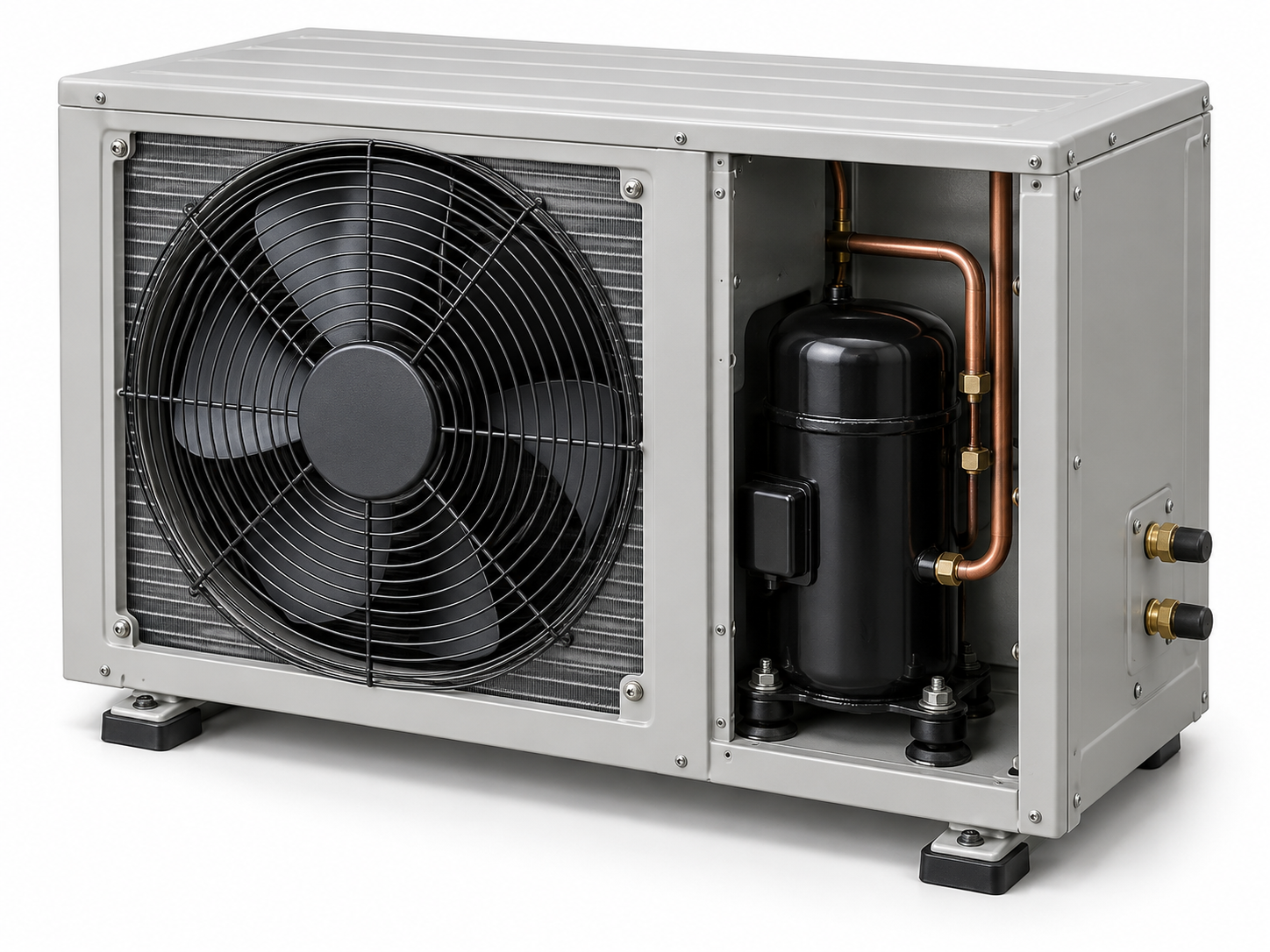
The condenser is the heat-rejection component of a condensing unit. The unit also includes a compressor and other circuit components, which are not parts of the heat-transfer coil.
For heating and hot water
An exchanger transfers heat between the source and the heating or domestic hot-water circuit. Specify both circuits, water quality and the required temperatures; a radiator and a central heat exchanger have different roles.
For drying chambers and timber kilns
Identify the chamber process and the component being selected: an air-heating coil, a dehumidifier exchanger or a heat-recovery element. Timber drying belongs here as a named application; the wood is the product being dried, not a heat exchanger material.
Timber drying: air, heat and moisture
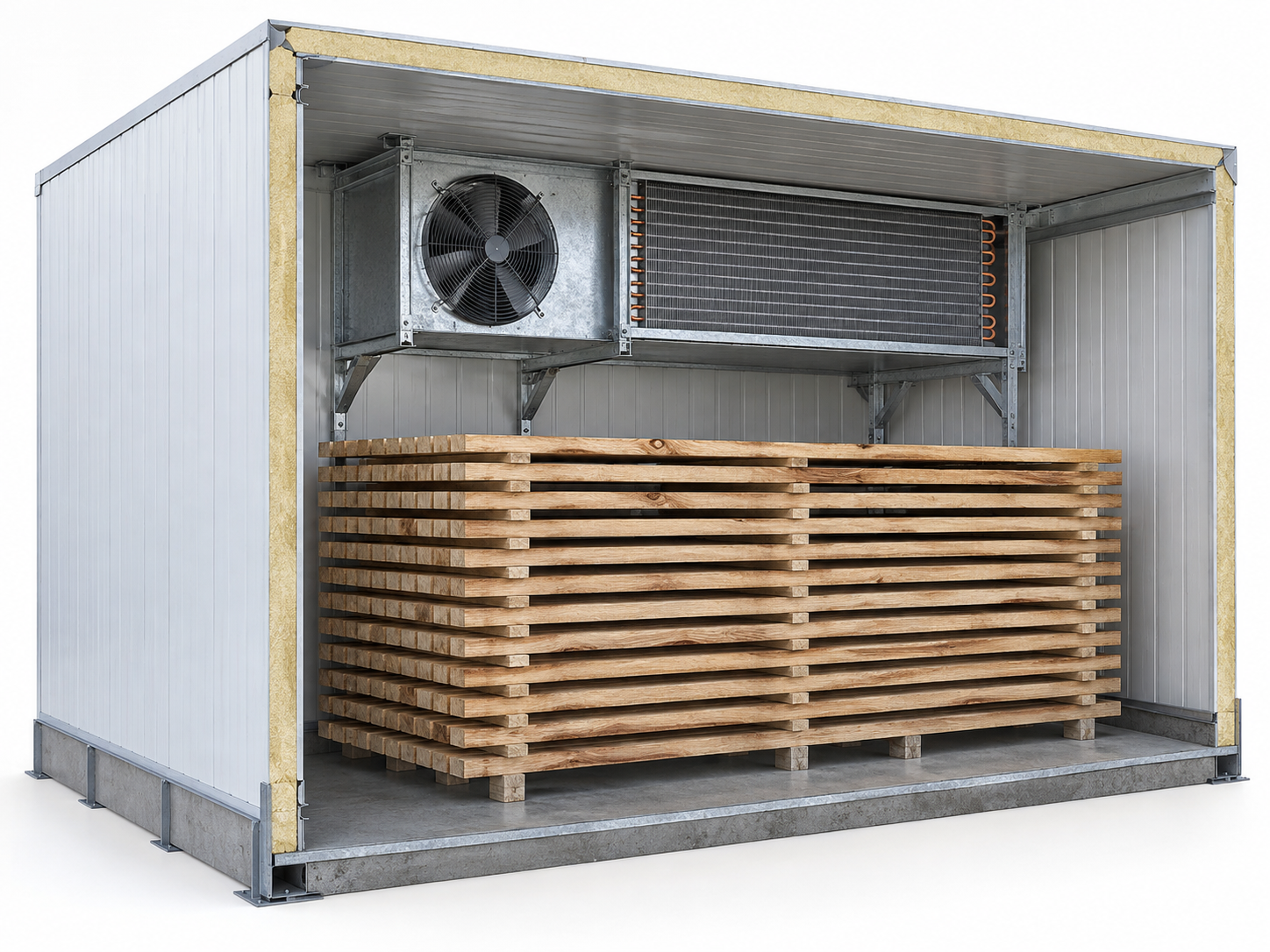
In a convective timber kiln, fans circulate air through the timber and heating coils. Heating, air circulation and moisture removal have different roles; replacing the coil does not by itself define the drying schedule.
For an enquiry, identify the wood species, board thickness, batch or continuous operation, initial and target moisture content, and the specified air conditions at each relevant stage. The responsible drying specialist establishes the process requirements.
Water, steam, electric heating or a heat pump
Record the actual heat source and circuit. A liquid-fed coil and a steam-fed coil require different input data. If the chamber uses electric resistance elements, identify that assembly separately instead of requesting a water coil by the chamber name.
Heat-pump dehumidification is another timber-drying arrangement. Identify whether the required component heats the air, cools it to remove moisture, or transfers recovered heat; the drying application does not make these exchangers interchangeable.
Operating data for a drying coil
Specify the air volume flow and entering and required leaving air conditions, including humidity where relevant. Give the operating range and the demanding stages of the cycle; a single nominal temperature or chamber volume does not describe the full duty.
For the heating side, state the medium, inlet conditions, flow or agreed thermal duty and design limits. Keep operating or design pressure separate from allowable pressure drop. For steam, also identify the supply condition and condensate-removal arrangement.
Replacing a chamber section
Provide the nameplate, photographs, finned and overall dimensions, mounting points, connection positions and removal access. Record the circuit layout where known. State the actual atmosphere, contamination and cleaning method for a materials review.
Identify moisture-removal and heat-recovery equipment separately from the heater. The enquiry should say whether the failed item is the heating section, a dehumidifier coil or an exhaust-heat exchanger, and describe the observed fault.
For dehumidifiers
First distinguish condensation and desiccant equipment. Their moisture-removal methods and thermal components differ. Identify the actual evaporator, condenser, air-treatment coil or regeneration heater before specifying a replacement.
Condensation: evaporator and condenser
In a condensation dehumidifier, the evaporator cools moist air so that water condenses and drains away. The air then passes through a condenser that reheats it. These are distinct components of the refrigeration circuit.
Identify the faulty component by its circuit and location. Provide the model and refrigerant, operating air conditions, circuit arrangement and condensate or defrost requirements. Do not use “dehumidifier radiator” as the only part description.
Desiccant equipment and regeneration
A desiccant rotor removes moisture from the process air and is regenerated through a separate air stream. The rotor is a moisture-transfer element; it must not be described as the same component as a finned heating or cooling coil.
Identify the regeneration heat source and any separate pre- or post-treatment sections. Manufacturers offer different regeneration arrangements, including steam and electric heating; specify the installed arrangement before discussing a replacement heat exchanger.
What to include in an enquiry
State the intended temperature and humidity range, airflow and required moisture removal at a stated condition. Provide the equipment model, identified component and service history. A capacity figure without its reference air conditions is incomplete.
For the exchanger, include dimensions and connections, working medium, temperatures, pressure limits and permitted pressure drops. Describe exposure and cleaning separately. Condensate collection, drainage, controls and the exchanger itself are different parts of the system.
For greenhouse heating and dehumidification
Identify whether the exchanger heats or cools greenhouse air, operates in a dehumidifier, or separates water circuits. The greenhouse application alone does not define one coil type or a universal replacement.
Air-heating coil or water-circuit exchanger?
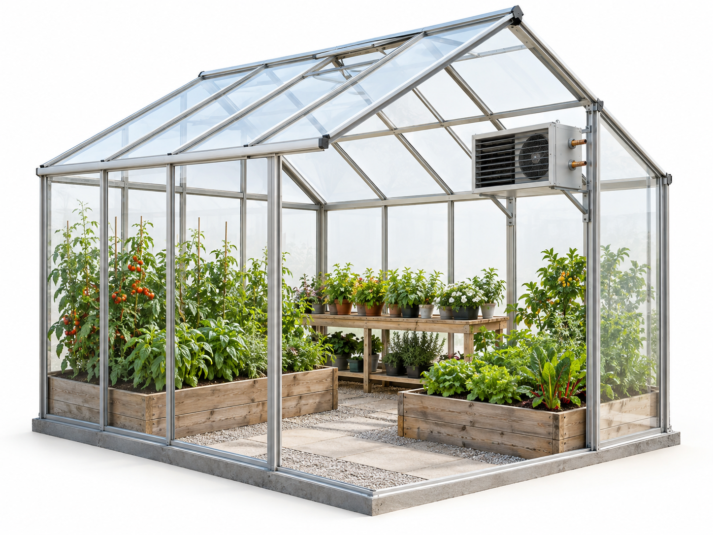
A water-fed air heater transfers heat between water and greenhouse air. A separate fluid-to-fluid exchanger, where present, transfers heat between two hydraulic circuits. Identify which pair of media is involved before selecting a construction.
Record the installation and system diagram. Pipe heating, an air-heating coil and a circuit-separating exchanger are different system elements; similarity in the heating application does not establish dimensional or functional interchangeability.
Humidity control and additional heating or cooling
Greenhouse dehumidification equipment can combine its moisture-removal system with a separate hot- or cold-water air coil. The water coil is supplied by an external source and adjusts the temperature of the treated air.
For replacement, distinguish that water coil from the dehumidifier’s refrigeration components. State which function is affected—air temperature, moisture removal or water circulation—and provide the component identification and observed symptoms.
Climate and replacement data
State the required air temperature and humidity range, operating periods, airflow where applicable and the available heat or cooling source. Separate the overall greenhouse load from the duty of the specific exchanger being selected.
Provide the fluid and its composition, entering and leaving temperatures, flow, pressure limits and permissible pressure loss. Add photographs, mounting and connection dimensions, exposure to moisture or chemicals, and the cleaning method.
For process equipment and production lines
Start with the actual thermal task: cooling a machine circuit, heating or cooling a product, or recovering heat. Identify the two media and the equipment involved. Drying chambers and dehumidifiers have their own named topics in this guide.
Machine and production-line cooling
A request for a printing machine, conveyor or production line must name the actual cooled component and circuit. The machine name is a starting point for identification, not a specification of the exchanger construction or working fluid.
Provide the equipment model, actual medium, temperatures, flow, required duty and operating cycle. Keep circuit pressure separate from permitted pressure loss and describe contamination and access for service.
Heating or cooling a process product
Identify the product and service medium separately. State composition and relevant properties, including solids or viscosity where applicable. Distinguish an exchanger in contact with the product from one conditioning the air around it.
Describe the temperature change, throughput, process cycle and cleaning requirements before choosing a construction. Hygienic, corrosion or fouling requirements need evidence for the specific duty; an industry label alone does not establish suitability.
Process heat recovery
Identify both the available heat source and the receiving process. Record temperatures, flows, operating times and whether the streams are available together. Describe any limits on mixing, leakage or contamination between them.
For exhaust from a drying process, state the actual moisture and contaminant conditions and identify the recovery arrangement. Use the drying and dehumidification topics for the chamber or moisture-removal component rather than treating every item as a generic industrial coil.
Sizes, parts and connections
Back to contentsStandard sizes
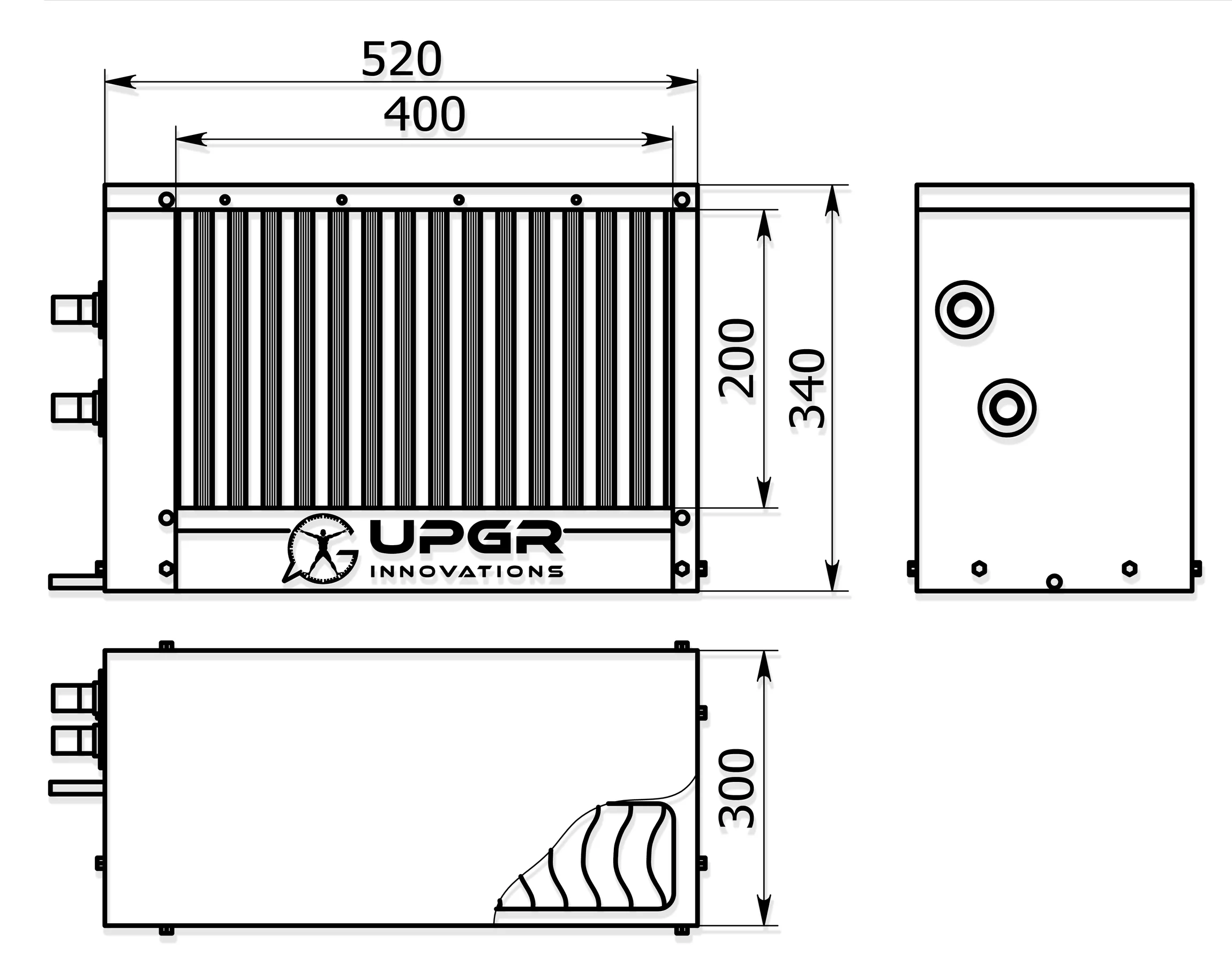
A standard size belongs to a particular manufacturer series. Face dimensions alone do not define capacity or interchangeability: rows, fin spacing, circuits and connections also matter.
Check interchangeability
- Series and revision
- Start with the manufacturer, series, nameplate and drawing revision. A nominal size is not a complete specification.
- Geometry and circuit
- Compare the finned area, depth, rows, connection side and circuit arrangement.
- Actual duty
- Confirm the thermal duty and pressure losses at the actual flow and temperatures. Equal external dimensions do not establish equal performance.
Custom sizes
A custom exchanger is specified by duty and installation constraints together. A dimensioned drawing records the agreed geometry, but a thermal calculation is still required.
Duct-mounted
A duct-mounted section connects to the ventilation duct. Circular or rectangular connections describe the installation; heating or cooling duty and the working fluid must be specified separately.
Parts and construction details
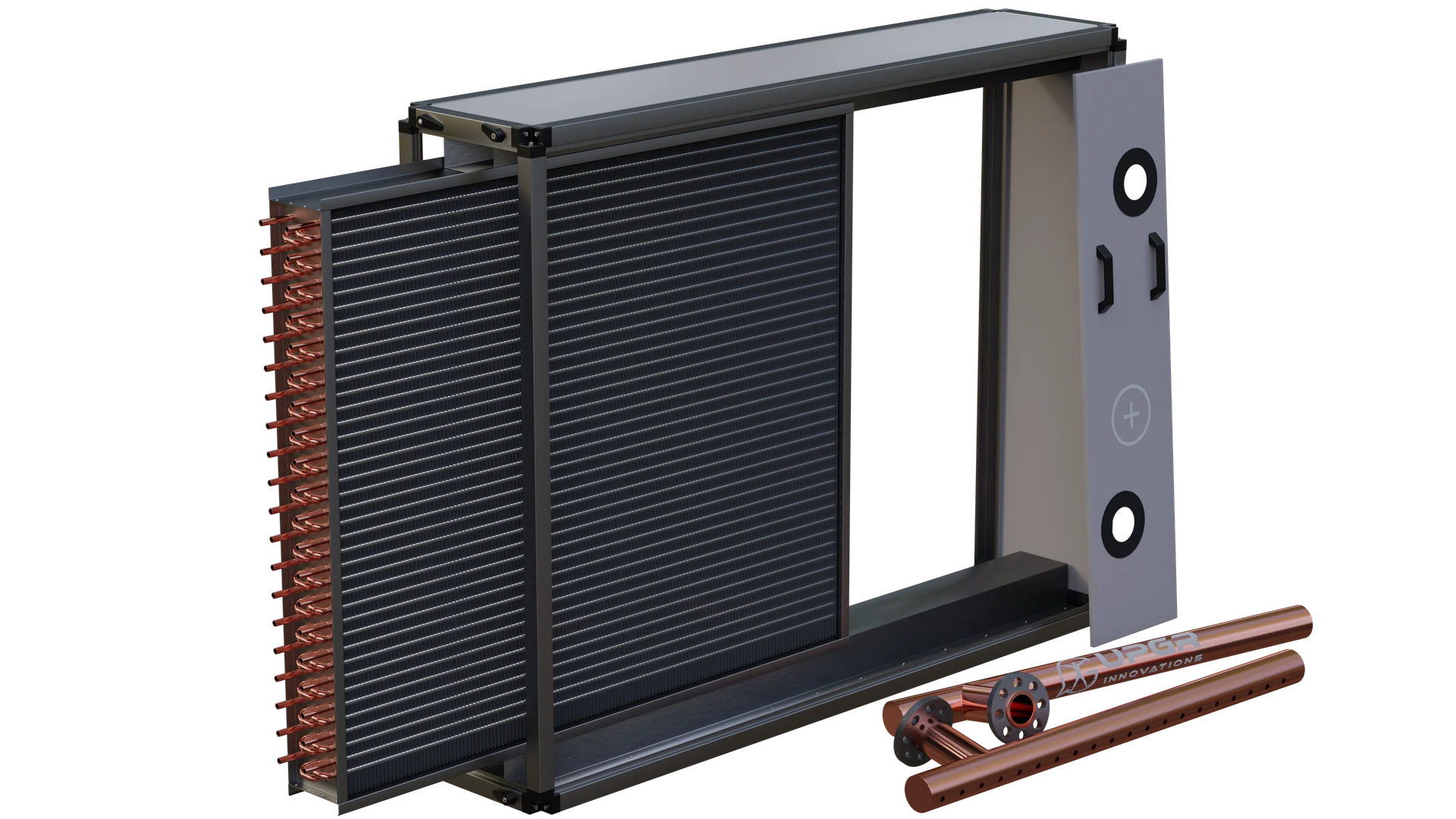
A finned coil contains tubes, return bends, fins, headers and a casing. A gasketed plate exchanger contains a plate pack, seals, frame and tightening components; parts must be identified for the actual construction.
What each part does
- Tubes and return bends
- Tubes carry the medium. Return bends join tube ends and create the required circuit path.
- Fins
- Thin fins extend the air-side heat-transfer area; damaged or blocked fins affect air passage.
- Headers and connections
- Headers distribute or collect flow between circuits. Connections join the exchanger to external pipework.
- Casing and supports
- The casing holds the finned pack and locates it in the equipment. Connection loads and mounting must be considered separately.
- Plates and seals
- In a gasketed plate exchanger, plates form the heat-transfer channels and seals separate the circuits and seal the plate pack.
Piping and mixing units
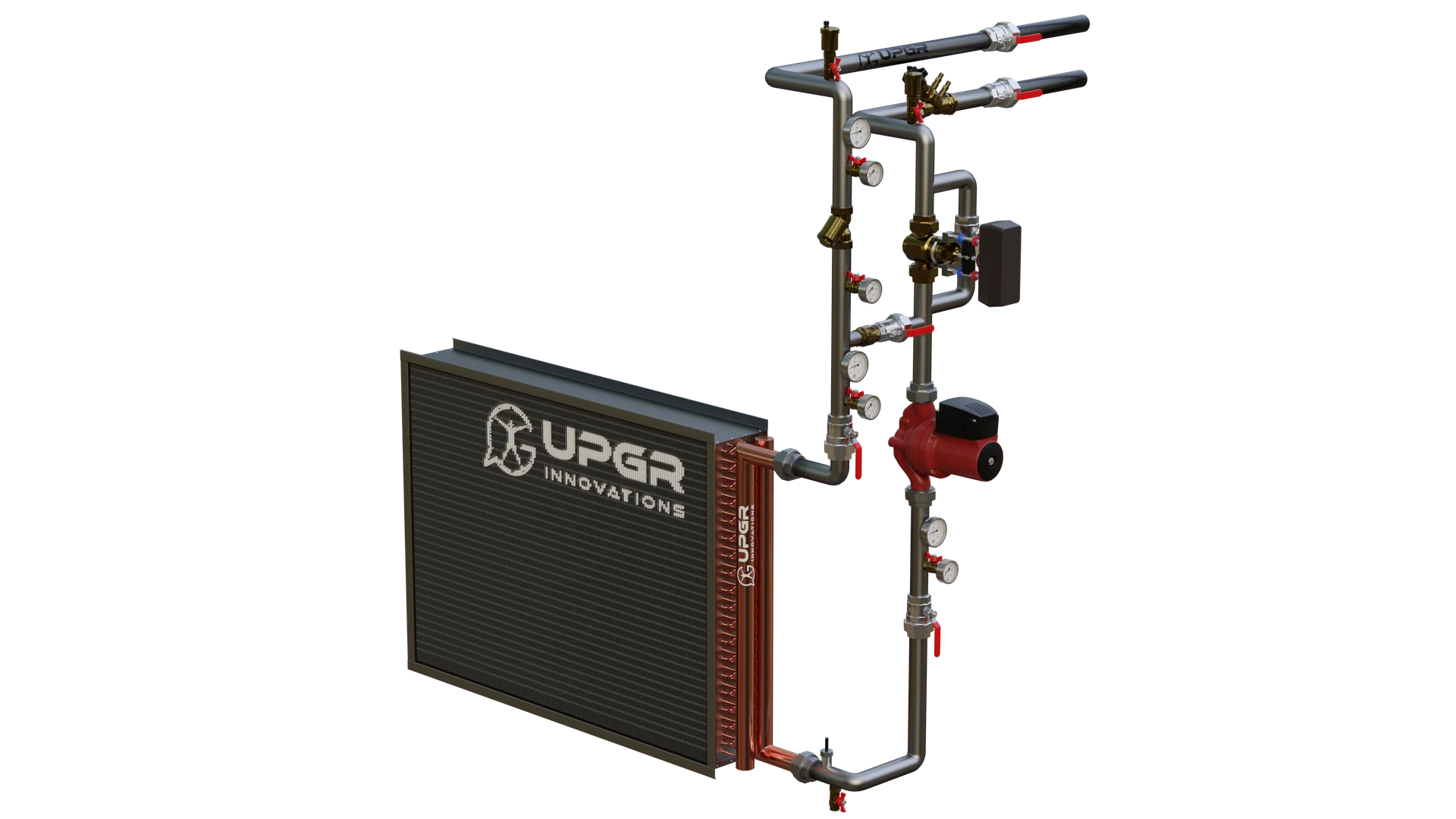
A liquid coil can be connected through piping, valves, a pump and a control assembly. These belong to the connected system; refrigerant expansion devices and condensate eliminators perform different functions.
Selection and service
Back to contentsCalculation and selection
Specify both media, temperatures, duty or flow rates, allowable pressure drops and installation constraints. These inputs are used for a thermal selection; the enquiry form collects them without calculating a rating.
Compare constructions before choosing a model
Use the differences below to frame the selection task. Duty, media and operating limits must be checked for the actual model.
| Construction | Flow arrangement | What matters for service |
|---|---|---|
| Gasketed plate | Fluids pass through alternating plate channels. | The pack can be opened; allow space to move the pressure plate and remove plates. |
| Brazed plate | Plates are joined into a compact sealed pack. | The pack cannot be opened for mechanical cleaning; check the permitted cleaning method. |
| Shell and tube | One medium flows in tubes, the other around them in the shell. | Access depends on the head, tube arrangement and whether the bundle is removable. |
| Finned tube | A medium flows in tubes while air passes across the fins. | Keep air passages accessible and provide a way to remove the coil; consider condensate if cooling. |
Data for a meaningful selection
- Both media
- Name both fluids. Include glycol type and concentration, refrigerant designation or the process-fluid composition where relevant.
- Operating point
- Provide inlet and required outlet temperatures, the required duty and the known flow rates. For air cooling, include humidity.
- Pressure and losses
- Distinguish operating/design pressure from the allowable pressure drop through the exchanger on each side.
- Installation and service
- State the available space, connection positions, materials, contamination and access for cleaning or removal.
Drawings and technical documents
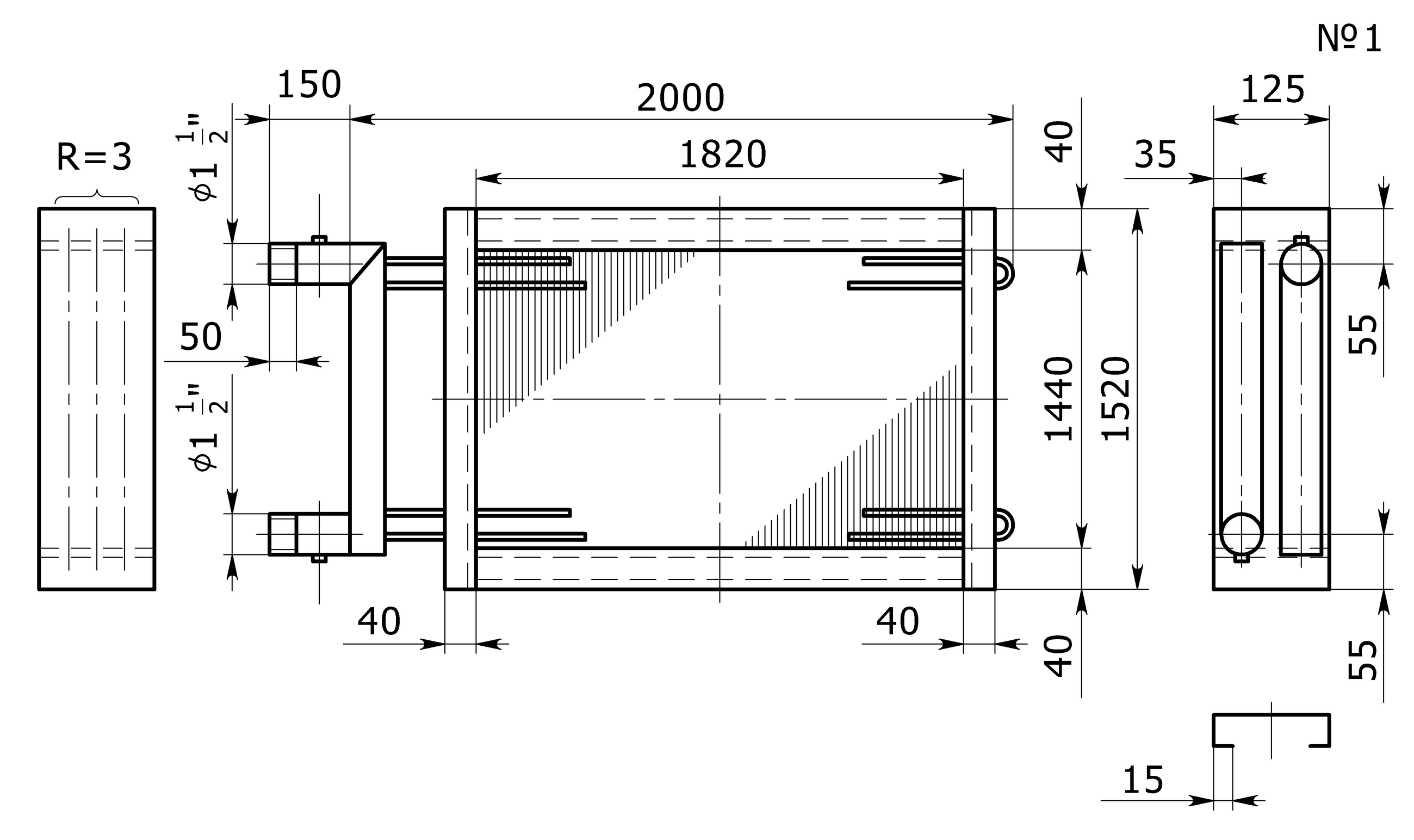
A drawing should identify the model, revision, dimensions, connection side and mounting points. A sample drawing explains construction; manufacture and acceptance require the agreed drawing and documents for the specific exchanger.
Which document answers which question
- Dimensioned drawing
- Shows size, mounting and connections. Confirm the viewing direction, connection side and revision.
- Selection sheet
- Records the media, temperatures, flow rates, duty and pressure losses for the selected operating point.
- Test record and instructions
- The applicable test record and operating instructions belong to the specific supplied product. A library illustration cannot replace them.
Manufacturing to requirements
Agree the duty, materials, circuit layout, connection positions and drawing revision. The specification also defines inspections and the documents supplied with the finished exchanger.
Diagnostics, repair and replacement
Record the symptom, location of the damage and operating history. Inspect the relevant tubes, fins, headers, plates or seals to assess repair versus replacement; the decision depends on construction and condition.
Cleaning and maintenance
Cleaning depends on deposits, materials and whether the exchanger can be opened. Use the manufacturer’s procedure; a method suitable for a removable plate pack may damage thin fins or an assembled brazed unit.
Price and quotation inputs
Compare quotes at the same operating conditions and drawing revision. Specify quantity, materials, included and excluded items, tests, documents, delivery location and required timing; mark unknowns for clarification.
Heater, cooler or radiator?
An air heater, often called a calorifier in Russian, describes a heating duty; an air cooler describes cooling. “Radiator” is broader and can mean an automotive or heating product, so specify the equipment and fluids.
Technical documents
For selection or replacement, collect the equipment nameplate, the dimensional drawing with connection positions, the working-fluid data and the required duty. Compare the selection report with the drawing revision; use the operating manual for installation, cleaning and service.