Corrugations and distribution area
The profile affects flow distribution, heat transfer and hydraulic resistance. Plate patterns are selected together with the duty and pressure-drop limit.
UPGR KNOWLEDGE · HVAC
A plate heat exchanger transfers heat between two fluids through thin metal plates while keeping the fluid paths separate. Its construction determines the materials, operating limits and access for cleaning.
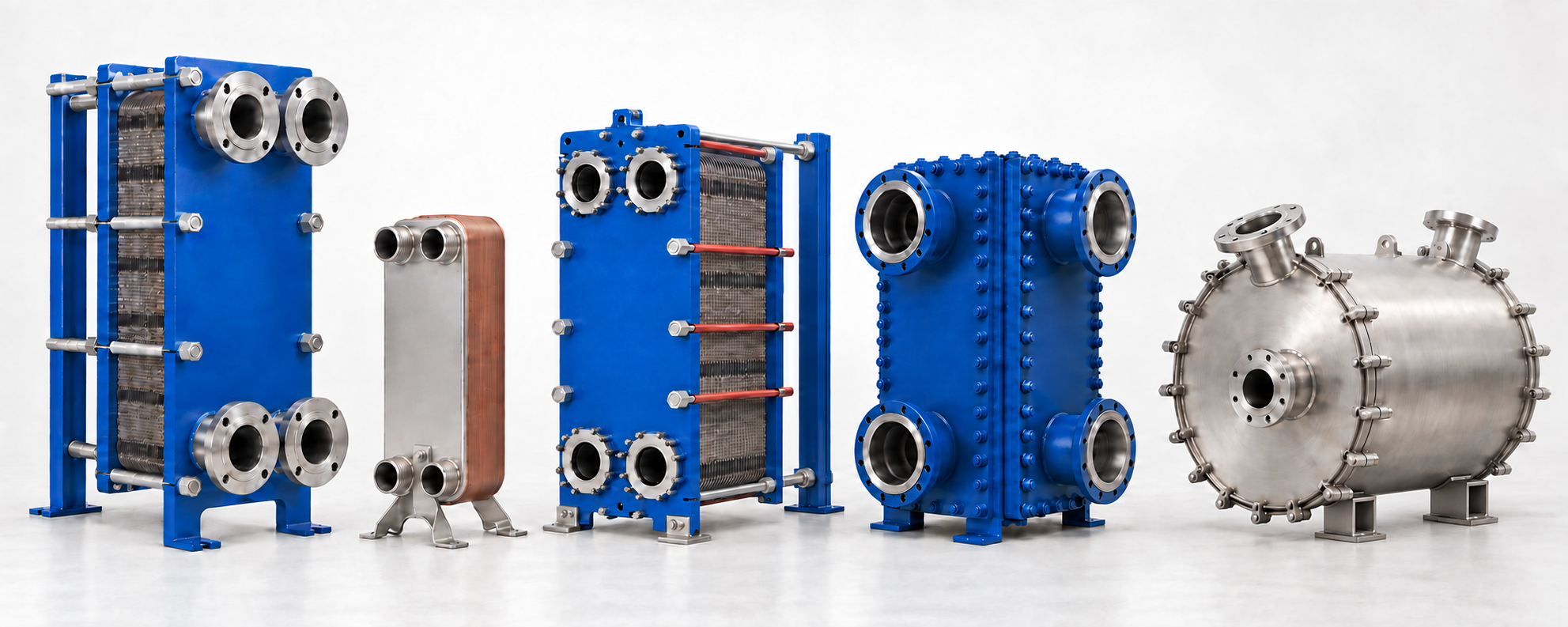
Main plate heat exchanger designs · from left to right
Illustration of typical designs at illustrative relative sizes. Gasketed and semi-welded units can share a similar frame; the plate joints inside differ.
View the image at full sizeOperating principle and designs
The fluids enter their assigned ports and flow through separate channels on opposite sides of the plates. Heat passes through the metal; the fluids remain separated in normal operation. Plate orientation and the sealing or joining arrangement establish the circuit paths.
Counter-current flow is common, but the actual flow arrangement and number of passes depend on the design and calculation. Gasketed frames open for plate access; permanently joined packs require another service approach.
The duties covered here are liquid-to-liquid heat exchange and evaporation or condensation in suitable plate designs. Air-to-air plate recuperators and plate-fin exchangers use different constructions and selection criteria.
Two circuits. Heat through a wall.

Two neighboring channels share one thin corrugated wall. The fluids flow on opposite sides without mixing in normal operation.
Compare the plate joints, access for cleaning and selection requirements. Welded units include both plate-pack and spiral designs.
| Construction | How channels are sealed | Access and cleaning | What to check first |
|---|---|---|---|
Gasketed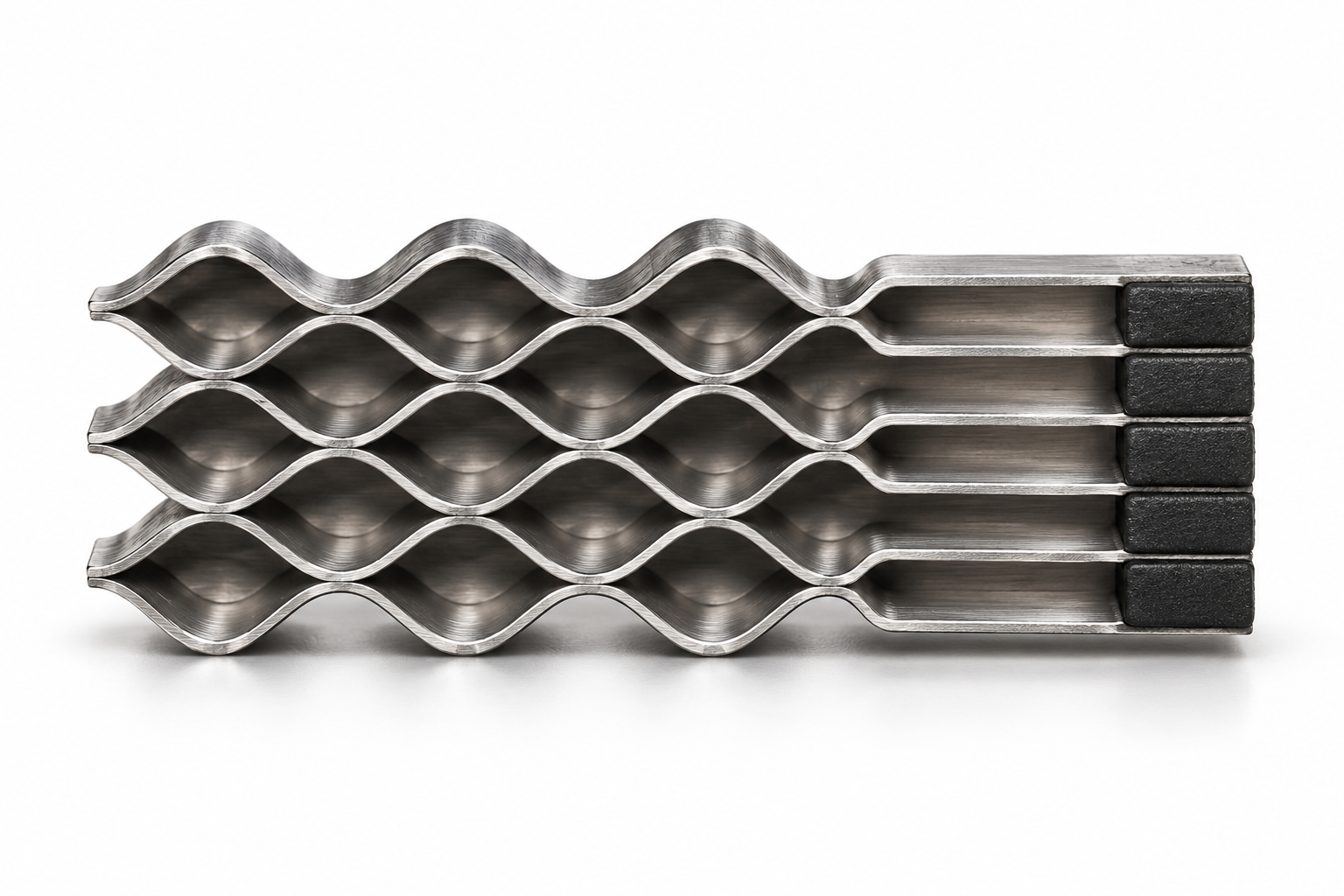 | Gaskets between plates | The pack opens for inspection and mechanical cleaning; cleaning without opening (CIP) is also possible. | Plate and gasket grades, opening space, assembly dimension. |
Brazed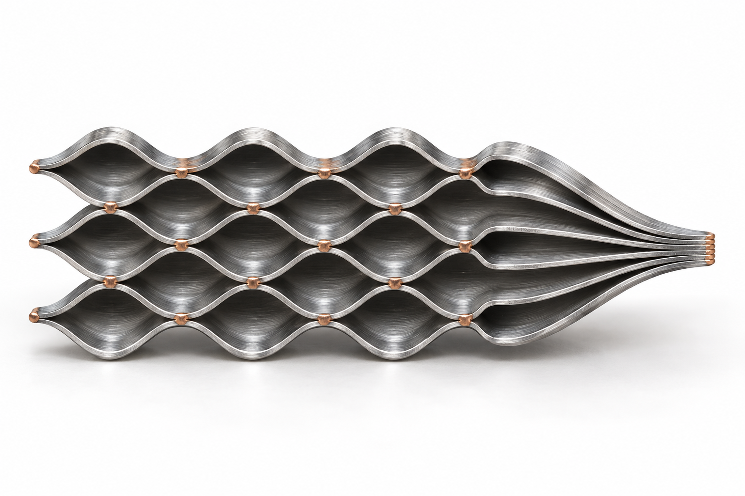 | Permanent brazed joints | The pack does not open. Confirm an approved cleaning process. | Filler metal, fluids and exact assembled configuration. |
Semi-welded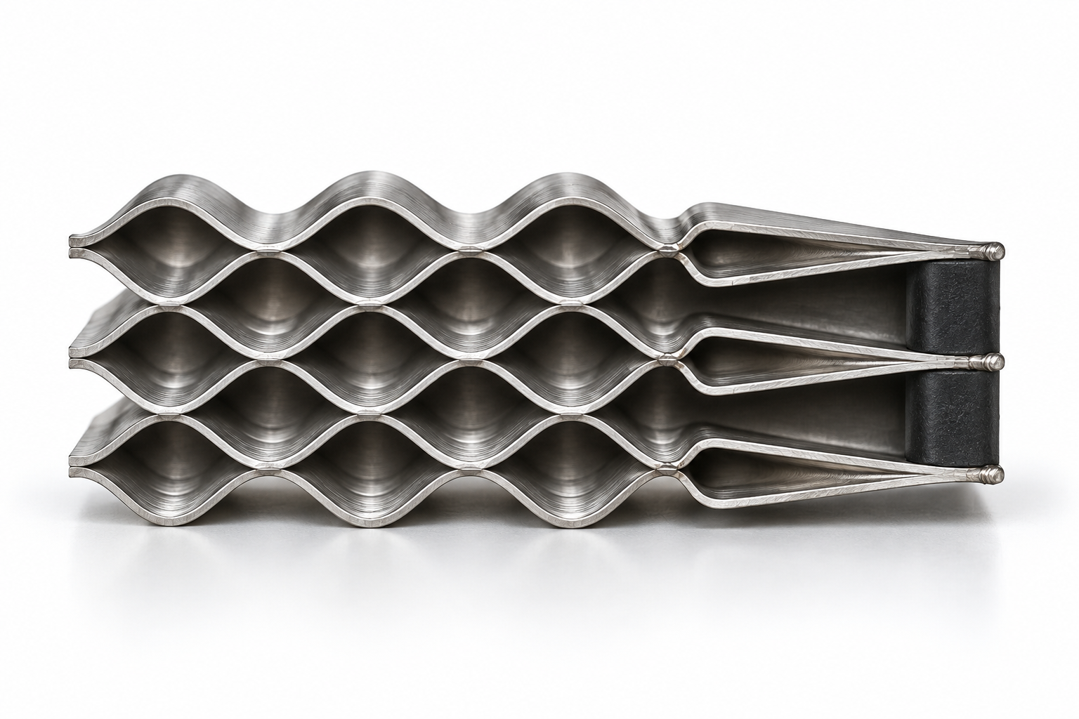 | Welded cassettes and gaskets | Access differs between the welded and gasketed channels. | Which fluid enters each channel, including port seals. |
Welded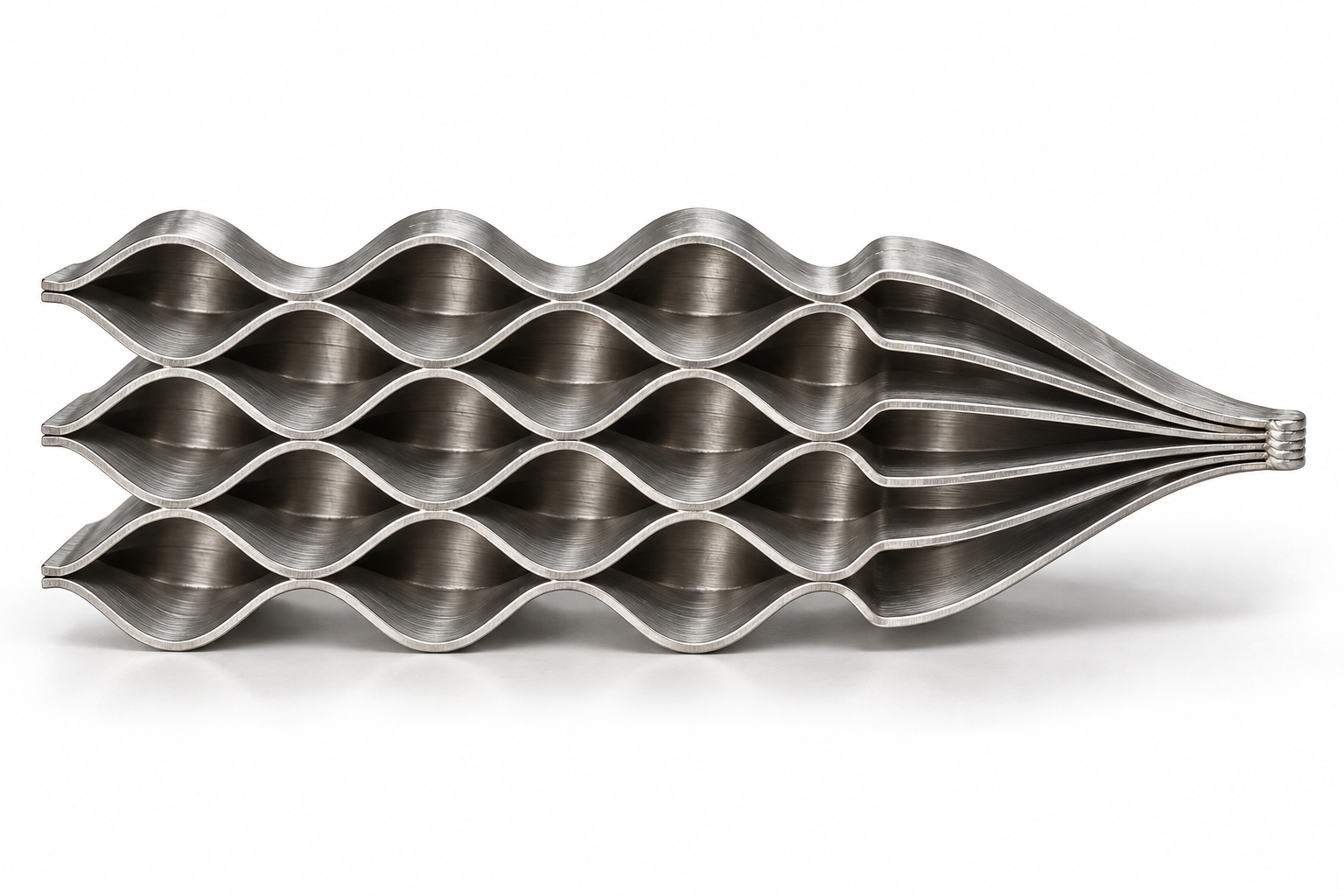 | Welded plate channels | Block and plate-and-shell designs have different service access. | Core/enclosure construction and manufacturer cleaning instructions. |
Spiral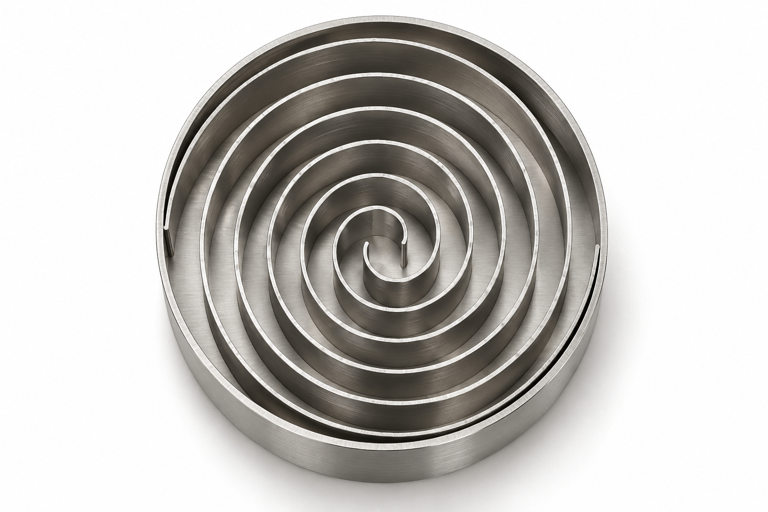 | Wound sheets forming two channels; typically welded | Cover access and flow arrangement depend on the design. | Solids, viscosity, fouling and channel geometry. |
Realistic sectional illustrations of construction details. Plate count, corrugations and joint locations are illustrative.
A compressed pack of plates and replaceable gaskets sits in a frame. Opening the pack gives access to the heat-transfer surfaces for inspection and cleaning.
The plates are permanently joined into a compact pack. It cannot be opened like a gasketed frame; service and replacement decisions depend on the fluid, fouling and joining material.
Pairs of plates form welded cassettes, with gasketed channels between them. This combines a welded side with access to the gasketed side; it is not the same as a fully gasketed or fully welded unit.
Welding joins the plate channels. Plate-and-shell and welded block units use different assemblies, covers and flow arrangements, so their service access and ratings must be checked separately.
Two metal sheets are wound to form two separate spiral channels. Spiral heat exchangers belong to the broader plate heat exchanger family; their channel geometry differs from a conventional corrugated plate pack.
Components
The detailed component list below describes a gasketed plate-and-frame heat exchanger, shown on the left in the main image. Plates and gaskets form the working pack; the frame supports and compresses it. Rollers, liners and some support elements depend on the frame execution. Brazed, semi-welded, welded and spiral designs have their own component lists.
A profiled metal sheet separates the fluids and transfers heat. Its corrugations, distribution area, port openings and gasket groove form one part.
The first, last and any pass-divider plates complete the specified flow arrangement. Their openings and gasket layout may differ from an ordinary channel plate.
The shaped elastomer gasket seals the plate perimeter and separates flow paths around the ports. Its profile follows the plate groove.
Separate ring seals or a special end gasket may be used at particular positions. The sealing arrangement is defined by the plate-pack drawing.
The stationary end of the frame carries the fixed side of the compressed pack and the bar attachments. Connections are often located on this plate.
The movable frame plate closes the pack against the fixed plate. It moves away from the pack to provide service access.
Supports the suspended plates and, in the relevant frame design, the pressure plate. Plates move along it when the pack is opened.
Locates the lower edges of the plates and helps keep the pack aligned. In the relevant design it also guides the pressure plate.
Supports the free ends of the frame bars in a column-type frame. Compact frames can use a different supporting arrangement.
Where fitted, a roller or carriage helps the heavy pressure plate travel along the carrying bar. Its position and construction vary by frame.
Apply the clamping force that compresses the plate pack between the fixed and movable plates. Their layout belongs to the frame design.
Nuts and washers transfer the tightening load. Some frames include bearing boxes or other friction-reducing hardware.
Connect the heat exchanger to external piping. They feed the internal port passages; a pipe connection and an opening in a thin plate are different elements.
A connection can have a metal or elastomer liner. Separate flange seals may also be fitted; their presence depends on the connection design.
Transfer the frame load to its foundation and provide the specified fixing points. Their arrangement depends on the frame.
The plate is the basic heat-transfer part. The assembled pack contains the specified number, sequence and combination of plates. A channel is the passage formed between neighbouring plates; it is not an additional replaceable part.
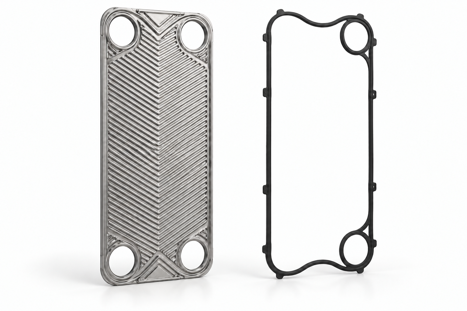
The corrugated metal surface transfers heat between the fluids.
Corrugations and distribution areaThe elastomer seal closes the channel boundaries and separates the fluid paths. In this example, the two rings on the right isolate two ports from the channel; the other two ports lie within the main field boundary.
Gaskets and sealsIllustration of the parts. Corrugations, gasket shape and port layout depend on the design.
The profile affects flow distribution, heat transfer and hydraulic resistance. Plate patterns are selected together with the duty and pressure-drop limit.
Open and closed ports, orientation and pass-divider positions define the circuit arrangement. The pack must follow its plate-hanging list.
The gasket must fit the groove, while the hanging features must fit the frame. These interfaces matter even when two plates look similar.
Replacement must account for the position and function of the plate, its alloy and thickness, not only its length and width.
Plate gaskets seal the channel boundaries and separate the paths of the two fluids. The equipment can also contain end-position seals, port rings and connection seals. These must be identified separately.
A perimeter gasket and a separate port ring have different geometry and positions in the pack. Use the plate code and sealing diagram to identify them.
Mechanical clips, hanging tabs and bonded systems require matching grooves and fitting procedures. Attachment method does not define chemical compatibility.
Select the actual gasket compound for the fluids, concentrations, operating temperatures and cleaning media. Material-family names alone are insufficient.
The fixed frame plate and the movable pressure plate receive the plate-pack tightening force. Support feet connect the frame to its base. These structural plates are distinct from the thin heat-transfer plates inside the pack.
The upper carrying bar supports the suspended plates. The lower guiding bar keeps their lower edges aligned. A rear column supports the bars where the frame uses this arrangement. A roller or carriage can assist pressure-plate movement.
During opening, the pressure plate moves away and the plates are spread along the carrying bar. Bar length, free travel and the method of removing plates are service requirements. The manufacturer’s procedure determines whether any bar section is removed.
Tie bolts or tie rods, nuts and washers apply and transfer the pack compression force. Some frames use bearing boxes. The tightening system is separate from the bolts or studs that attach the external pipe flanges.
The final compressed pack dimension, often designated A, comes from the documentation for the actual plate count and execution. Neither the bolt count, a tightening torque nor a single pack dimension is universal for all heat exchangers.
Connections join the external piping to the internal port passages. Depending on the execution, they include nozzles or flanged ports, studs, liners and flange seals. Their material and pressure rating must match the equipment specification.
Protective sheets, insulation and port filters are specified separately when the design provides for them. They have different functions: shielding, reducing heat exchange with the surroundings, or intercepting particles. They do not replace the core plates, gaskets or supporting frame.
Materials and fluids
Plate material, brazing alloy and gasket compound are selected separately for the fluids, temperatures and cleaning method. State the exact grades and compatible seals in the equipment specification.
Water-to-water duties include heating, hot-water preparation and cooling. Water composition, fouling tendency and the temperatures and flows on both sides determine the selection.
For water-glycol circuits, identify the glycol type, concentration and concentration basis. The actual mixture is required for thermal and hydraulic calculations.
For a refrigerant duty, identify the refrigerant, phase states and operating and design conditions on both sides. The refrigerant name alone does not determine whether a brazed, semi-welded or another verified design is suitable. Materials and pressure limits belong to the specific execution.
Applications
In a heat substation, distinguish the heating circuit from domestic hot water. Record the network and building temperature schedules, required load and available pressure drop on each side. A single building load does not describe both duties.
Record incoming cold-water and required hot-water temperatures, peak demand, recirculation conditions and water quality. Confirm the wetted materials and the documents required for contact with drinking water.
First identify the role of the exchanger in the chiller system: separating water or glycol circuits, or transferring heat directly from or to the refrigerant. These duties require different input data and are not interchangeable.
For liquid-loop separation, specify the actual fluid composition and concentration, temperatures, flows and allowable pressure losses on both sides. The chiller nameplate capacity does not replace the operating duty of this exchanger.
A plate evaporator or condenser operates directly in the refrigerant circuit. Record the evaporation or condensation conditions and the secondary-fluid duty separately. An exchanger separating two liquid circuits is a different task even when both are part of the same refrigeration system.
Define the heat-source and heating-system circuits, refrigerant and required operating modes. For reversible systems, provide the conditions for each mode.
Heat recovery uses heat from a warmer process stream to preheat another stream while keeping the two fluids separate. Describe both the available heat source and the heat demand; the presence of a warm discharge alone does not define a recoverable duty.
Provide temperatures, flows and operating schedules for both streams. If the modes change, list the required operating cases rather than a single nominal load.
Identify composition, fouling and allowable pressure losses. Compare material compatibility and cleaning access before choosing a construction.
Process heating, cooling and heat recovery depend on fluid composition, viscosity, solids and fouling. Channel geometry and access for cleaning are selected for these conditions.
Food heating and cooling require hygienic equipment, suitable product-contact materials and a validated cleaning process. The specification includes the product, temperatures and hygienic requirements.
Engineering and installation
Define the two circuits, connection scheme, control strategy and installation conditions. Provide access to connections and sufficient space for the intended maintenance method.
Thermal performance and pressure drop are checked for each specified operating condition. For reversible systems, describe heating and cooling conditions separately.
Check the heat duty using fluid properties, temperatures and flows on both sides. A nominal power value without its operating conditions is insufficient.
Compare each circuit’s inlet-to-outlet pressure drop at the specified flow with its allowable value. Keep this hydraulic limit separate from working pressure and the unit’s pressure rating.
Compare the calculated duty, pressure and temperature limits, materials, connections and dimensions. The selection result is a defined model and configuration with a calculation sheet and specification.
Manufacturing combines formed heat-transfer plates with the joining method of the design: gaskets, brazing or welding. The production documentation defines materials, assembly and the required tests.
Use the connection arrangement and installation drawing for the selected unit. Check supports, pipe loads, orientation and access for inspection and maintenance against the manufacturer’s instructions.
Operation and service
Monitor temperatures, pressures, flow rates and pressure losses in both circuits. Keep operating conditions within the specified limits and follow the unit’s startup and shutdown procedure.
Choose the cleaning method for the deposits, materials and unit design.
A compatible cleaning solution circulates through the exchanger without opening it.
Cleaning requires direct access to the heat-transfer surfaces; that access depends on the unit design.
Opening a gasketed frame gives access to the plates and gaskets. Leave the service space specified for that frame so the pressure plate and plates can move along the bars. The opening sequence and any removal of bars depend on the design and its operating instructions.
Separated plates on the carrying bar
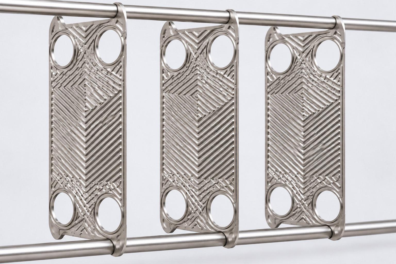
Detail of an opened plate pack. The plates are shown without gaskets to expose the corrugations and sealing grooves. Plate removal, cleaning and gasket replacement follow the instructions for the specific unit.
Isolate both circuits, depressurize them, bring the unit to a safe service temperature and drain it. Before loosening the tightening hardware, record the plate sequence, gasket arrangement and specified compressed pack dimension.
Release the specified tightening hardware and move the pressure plate as instructed. The carrying bar supports the suspended plates; the lower guiding bar locates their lower edges.
Check plate surfaces, gasket grooves and seals. Separate the plates as required for access, preserving their sequence. Use a cleaning method compatible with the plate and gasket materials and permitted for that unit.
Restore the plate and gasket arrangement, align the pack and tighten it to the specified compressed dimension using the prescribed sequence. Complete the required sealing checks before returning the unit to service.
Start with the symptom: loss of thermal performance, rising pressure loss or leakage. Compare operating readings with the specified duty and inspect the fluid condition, connections and accessible seals.
Compare inlet and outlet temperatures and flows on both sides with the specified duty. A change in available flow or inlet temperature must be distinguished from a change in exchanger performance.
Compare pressure loss at comparable flow and fluid conditions. Record which side changed before assessing fouling or flow restrictions.
Record the observed location, external traces, pressure conditions and equipment identification. The symptom alone does not identify a plate, gasket or connection as the failed part.
Repair options depend on the construction and identified damage. For a gasketed pack, inspect plates and gaskets; for permanently joined units, confirm the permitted repair or replacement with the manufacturer.
Begin with the nameplate, full model designation, connection drawing and previous operating duty. Verify thermal, hydraulic and installation compatibility for the replacement.
A spare-parts request can cover the following groups. Availability and replaceability depend on the particular equipment.
Provide the nameplate, equipment and component codes, relevant drawings or parts lists, photographs of the marked item, and quantities. For permanently joined units, establish whether the manufacturer supplies the complete core or exchanger rather than individual internal parts.
Carrying and guiding bars, the pressure-plate roller and support parts.
Equipment and supply
The equipment documentation includes the specification, calculation sheet, dimensional and connection drawings, operating manual and applicable conformity documents. Identify the model, configuration and document revision when comparing records.
Request the calculation sheet for the stated duty, the configuration specification and the dimensional and connection drawing. A general catalogue is not the calculation sheet of a selected unit.
Check the equipment identification, the applicable operating manual and the documents required for the supplied execution. Document requirements depend on the unit and project.
Use the serial number, plate-hanging or assembly list and part references from the equipment documentation. Check that the drawing and parts list apply to the installed execution.
The price of a plate heat exchanger is compared for a specified duty and configuration. Construction, materials, plate pack, connections and included equipment affect the scope of an offer. A model name or a nominal kW value alone is insufficient for a like-for-like comparison.
Compare the same fluids, temperatures, flows, allowable pressure losses, material requirements and installation constraints. Use the calculation sheet and specification.
Check whether insulation, supports, connection accessories, spares and required documents are included or priced separately. Record quantity and the exact execution.
Use the price, currency, delivery terms, lead time and warranty stated in the specific current offer. A catalogue description does not confirm stock or a delivery date.
Equipment specifications are compared after the duty, materials, connections and service requirements have been defined.
View the available plate heat exchanger modelsPrepare a specification from the data you know. Review and complete the resulting text before sending it to an engineer. This form does not send the request.
Prepare a selection brief