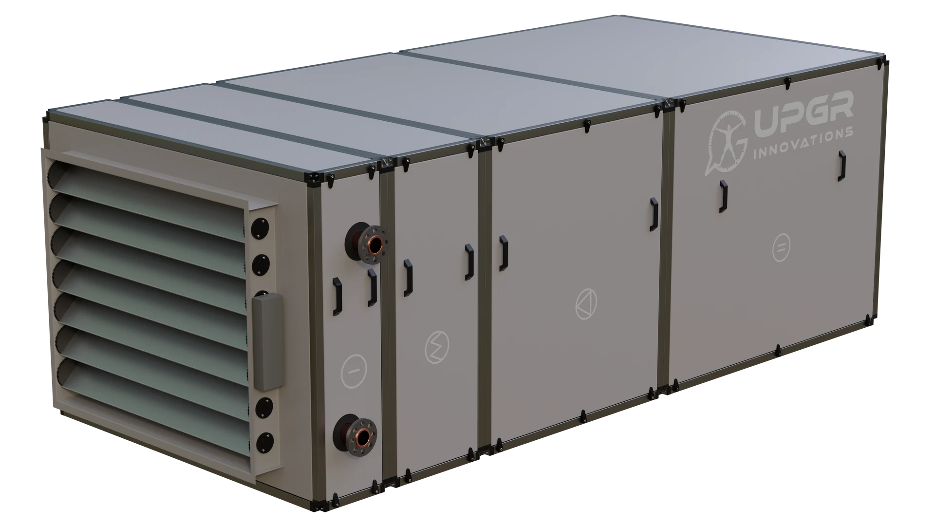
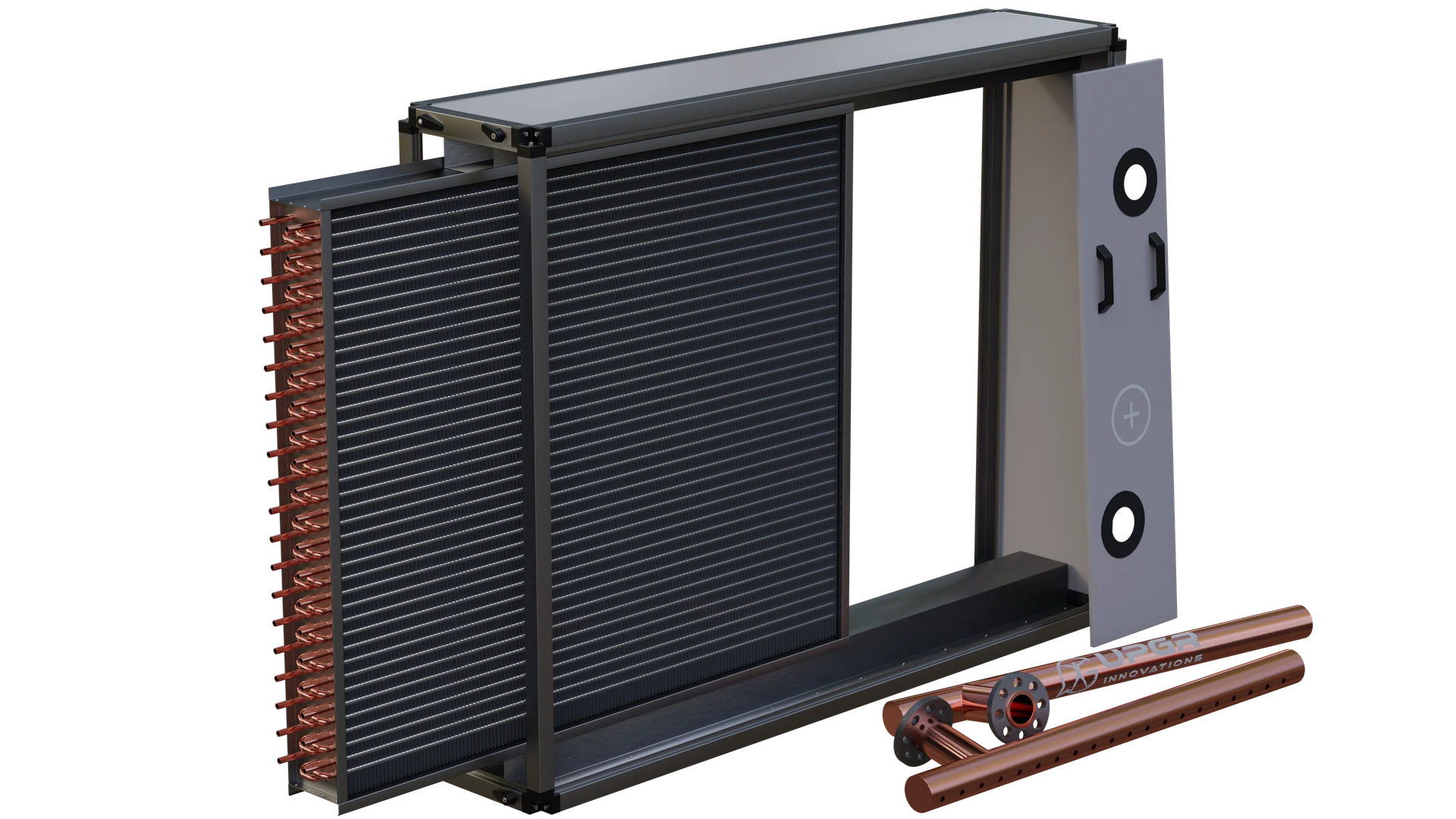
Sectional ventilation unitUPGR archive 3D visualization of a sectional ventilation unit. The closed casing does not establish the internal section order or airflow direction.Separate disassembly exampleUPGR archive 3D visualization: a disassembled AHU section. Headers and cover are separated to show access; this is not an operating condition.
01
The coil in a run-around loop
In a liquid-coupled recovery system, extract and supply coils are linked by a fluid loop and can occupy separate air paths. This differs from plate or rotary recovery; heat transfer in the extract system does not by itself establish a Cu-Al construction.
IN PRACTICE
The unit and an accessible coil section
A closed-unit example and a separate disassembly view explain the enclosure and the component level.
01
Unit envelope
The exterior view shows panels and connection areas, not the internal section sequence.
02
Coil section
The separate open view makes the finned block and removed components visible.
03
Actual duty
Confirm the coil function and operating conditions from the unit documentation.
The two illustrations are separate archive examples. Airflow and heat-recovery function are not inferred from the closed casing.
02
Replacing one coil affects the paired system
Checking an extract coil requires information about the supply side and the shared fluid loop. Compare both airflows and air states, fluid temperature and flow, coil pressure drops and circulation conditions. Recovery effectiveness cannot be assigned as a fixed percentage from one photograph or coil size.
03
Moist or contaminated extract air
State humidity, potential contaminants and cleaning access. If surface condensation is expected, check the drain pan and drainage; in cold operation, assess frost risk and its control response. Do not transfer materials, fin spacing or protection arrangements from an ordinary supply coil without checking the extract environment.
04
Identification and measurement
Identify the extract coil on the unit diagram and show its links to the circulation assembly and supply coil. Record the frame, opening, connection side and removal access. If the component is a plate exchanger, the enquiry must follow that construction; a Cu-Al coil is not a direct substitute.
REVIEW THE RESULT
What to check in an extract recovery coil
Thermal balance of the paired coils
Compare the extract and supply coil duties together with intermediate-fluid flow. Record both entering air states and the calculation boundary; do not assign constant effectiveness without this paired assessment.
The common hydraulic loop
Check fluid type and concentration, both coil and pipework resistances, and pump operating conditions. Coordinate the replacement with the remaining loop, not only the mounting envelope.
Condensate, frost and cleaning
Assess condensation and frost from surface temperature and extract-air state, then agree drainage and the protection response. Check contaminants and fin access separately; glycol content does not prove that the air-side surface remains frost-free.
SELECTION INPUTS
Inputs to prepare
Recovery type and a diagram linking the extract and supply sections.
Airflows, temperatures and humidity for both airstreams.
Loop-fluid type and concentration, temperatures and flow rate.
Paired-coil data, pump information and available head where known.
Extract contaminants, cleaning requirements, condensate handling and frost protection.
Dimensions, connections and photographs of the replacement coil and surrounding components.
What do you need to do?
Select a new coil
Define operating conditions first. The input checklist above describes the data needed for this application. The enquiry form adapts to the selected duty; it does not calculate a coil rating.
Add the equipment nameplate, photographs, overall and finned dimensions, airflow direction, connections and access constraints. Matching the envelope alone does not confirm performance or compatibility.
Separate fixed interfaces from dimensions open to change. Attach the current drawing revision, duty points, material requirements, quantity and acceptance criteria. Manufacturing feasibility is confirmed for the specific specification.
Final performance, materials and compatibility require a project-specific selection and an approved drawing.
Questions about this application
Is every aluminium heat-recovery exchanger a Cu-Al coil?
No. Material alone does not identify the technology. A plate block and a finned-tube coil have different flow paths and selection requirements.
Can the extract coil be replaced without supply-coil data?
Measurement can start independently, but checking run-around recovery performance needs the paired coil and common loop. Keep unknown parameters explicitly identified in the enquiry.
Does glycol eliminate air-side frosting?
No. Protecting the loop fluid from freezing and preventing frost on a surface exposed to moist air are separate issues. Both airstream conditions and an agreed protection response are needed.