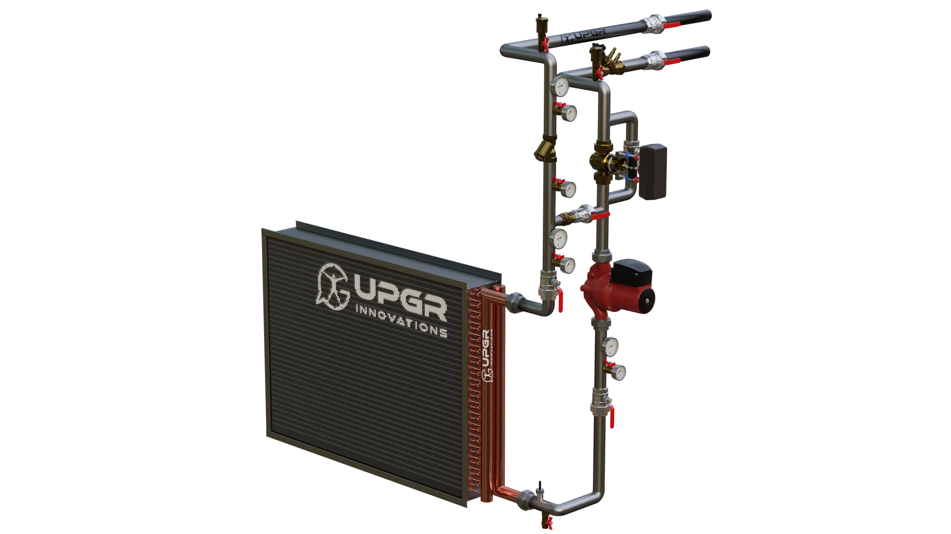
A mixing assembly is a separate piping package. Its components follow the coil duty and the site's hydraulic arrangement, not a photograph of an existing package.
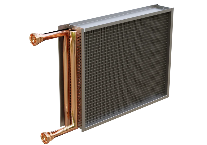
Piping layout exampleUPGR archive 3D visualization. A coil with piping is shown as a layout example, not an installation diagram. The piping package is specified separately.Connection-side viewArchive 3D connection-side view. Connection positions are illustrative; no dimensions or hydraulic circuit are established by this image.
01
Define the requested package
List the coil and its piping package separately. State whether the scope requires a pump, actuated control valve, strainer, isolation and balancing devices, sensors and controls. This is a list to agree: the name mixing assembly does not establish that every item or a complete control system is included.
IN PRACTICE
Coil connections and a piping layout
The archive layout introduces the piping assembly; the separate coil view shows its connection side.
01
Coil interface
Define the required connection sizes and positions.
02
Piping assembly
Use the layout to discuss the available space and component scope.
03
Hydraulic design
The pump, valve arrangement and controls are selected from the project duty.
The piping render is a layout example, not an approved installation or hydraulic diagram. The separate coil view is not a verified matching item.
02
Flow, resistance and the control valve
Provide supply and return fluid temperatures, required flow, coil resistance and available differential pressure at the connection point. Two-way or three-way arrangements and the need for a local pump depend on the hydraulic design. Connection diameter alone does not establish valve flow capacity or the pump operating point.
03
Controls and shutdown conditions
Agree the actuator control signal, power supply, feedback and response to fan shutdown or power loss. Cold outdoor-air service also needs an explicit water-coil freeze-protection strategy. A valve's appearance does not establish its required safe position or operating sequence.
04
A project diagram and an illustrative image serve different purposes
Installation needs an agreed document showing flow direction, port identification, components and connections. A render helps identify parts but does not define a universal hydraulic circuit. When replacing an existing assembly, first record its actual connections and settings, then document the agreed changes.
REVIEW THE RESULT
What to check in a coil piping package
Valve and pump operating point
Relate flow, coil resistance and available differential pressure to the selected hydraulic circuit. Check valve flow capacity and pump characteristics for the actual fluid; matching port diameters is insufficient.
Components, ports and flow direction
Agree the component schedule, inlet and outlet identification, orientation and service access. A package render may explain its components, but installation follows the approved project-specific diagram.
Control sequence and supply boundary
Check actuator power and signal, interlocks, fan shutdown and loss of power. Separately record who supplies sensors and the controller and how the coil is protected; a complete piping assembly does not establish complete controls.
SELECTION INPUTS
Inputs to prepare
Coil function: heating, cooling, recovery or another duty; working fluid.
Fluid temperatures, flow and coil pressure drop at the specified operating point.
Network diagram, available differential pressure and existing pump data.
Proposed component list and the control-system supply boundary.
Control signals, electrical supply, required interlocks and shutdown modes.
Connection sizes, available space, orientation and service access.
What do you need to do?
Select a new coil
Define operating conditions first. The input checklist above describes the data needed for this application. The enquiry form adapts to the selected duty; it does not calculate a coil rating.
Add the equipment nameplate, photographs, overall and finned dimensions, airflow direction, connections and access constraints. Matching the envelope alone does not confirm performance or compatibility.
Separate fixed interfaces from dimensions open to change. Attach the current drawing revision, duty points, material requirements, quantity and acceptance criteria. Manufacturing feasibility is confirmed for the specific specification.
Final performance, materials and compatibility require a project-specific selection and an approved drawing.
Questions about this application
Does every heating coil need the same three-way valve assembly?
No. The control arrangement must suit the network, coil duty and control system. An example package does not replace checking those conditions.
Can the pump be selected from heating-coil capacity alone?
Capacity alone is insufficient. Selection needs the required flow and resistance of the served circuit, accounting for the fluid and network operation.
Can the piping be installed from a 3D image?
Installation requires an agreed diagram and component documentation. An image does not establish every port function, flow direction or electrical connection.