Supply air handling unit
The casing guides supply air through its sections. A water, glycol or DX coil heats or cools the air; access panels and removable elements allow servicing.
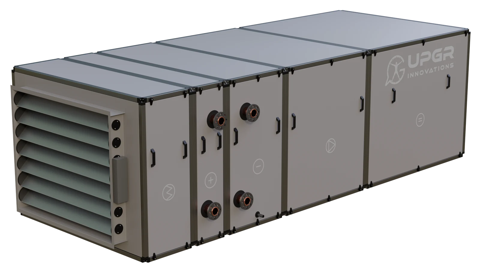
By equipment
Establish the air condition entering this particular coil and the required condition leaving it. Then match the duty and mounting arrangement to the supply air unit.
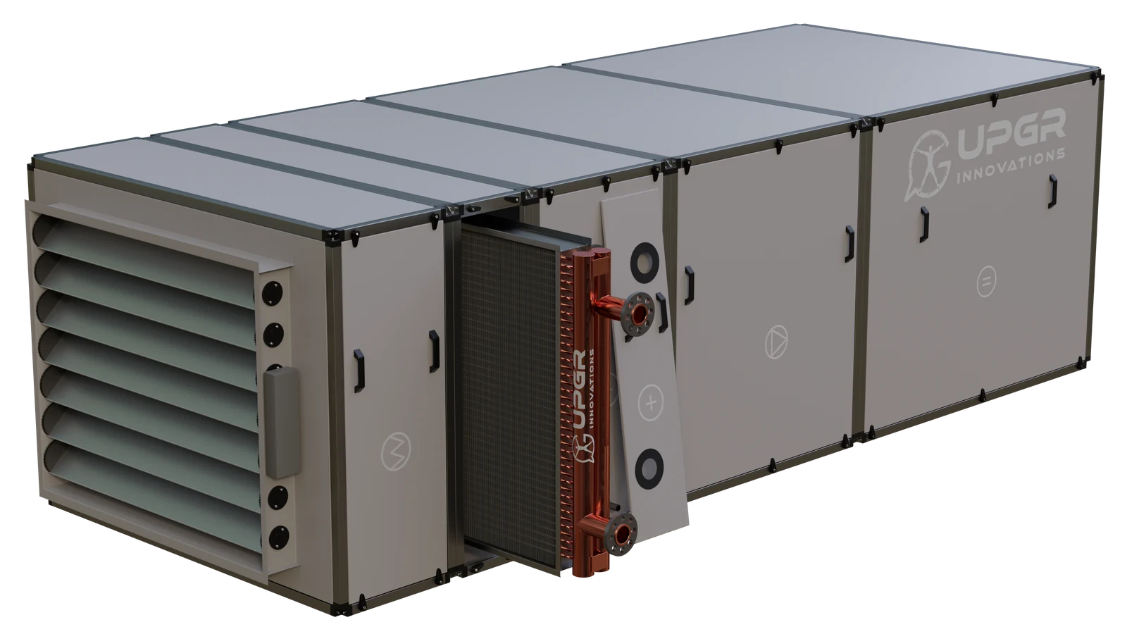
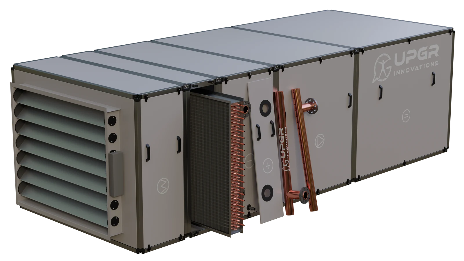
Compare the complete unit, access to the coil and an exploded view. These examples show the relationship between the equipment casing and the heat-transfer section.
The casing guides supply air through its sections. A water, glycol or DX coil heats or cools the air; access panels and removable elements allow servicing.
The two-level arrangement illustrates separate air paths. Heating, cooling and recovery coils have distinct duties. A run-around recovery system uses coils connected by a liquid loop; plate and rotary air-to-air exchangers use a different construction.
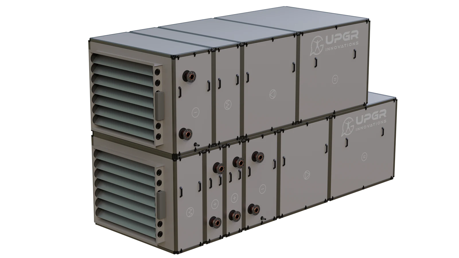
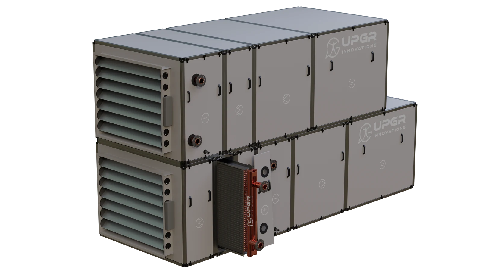
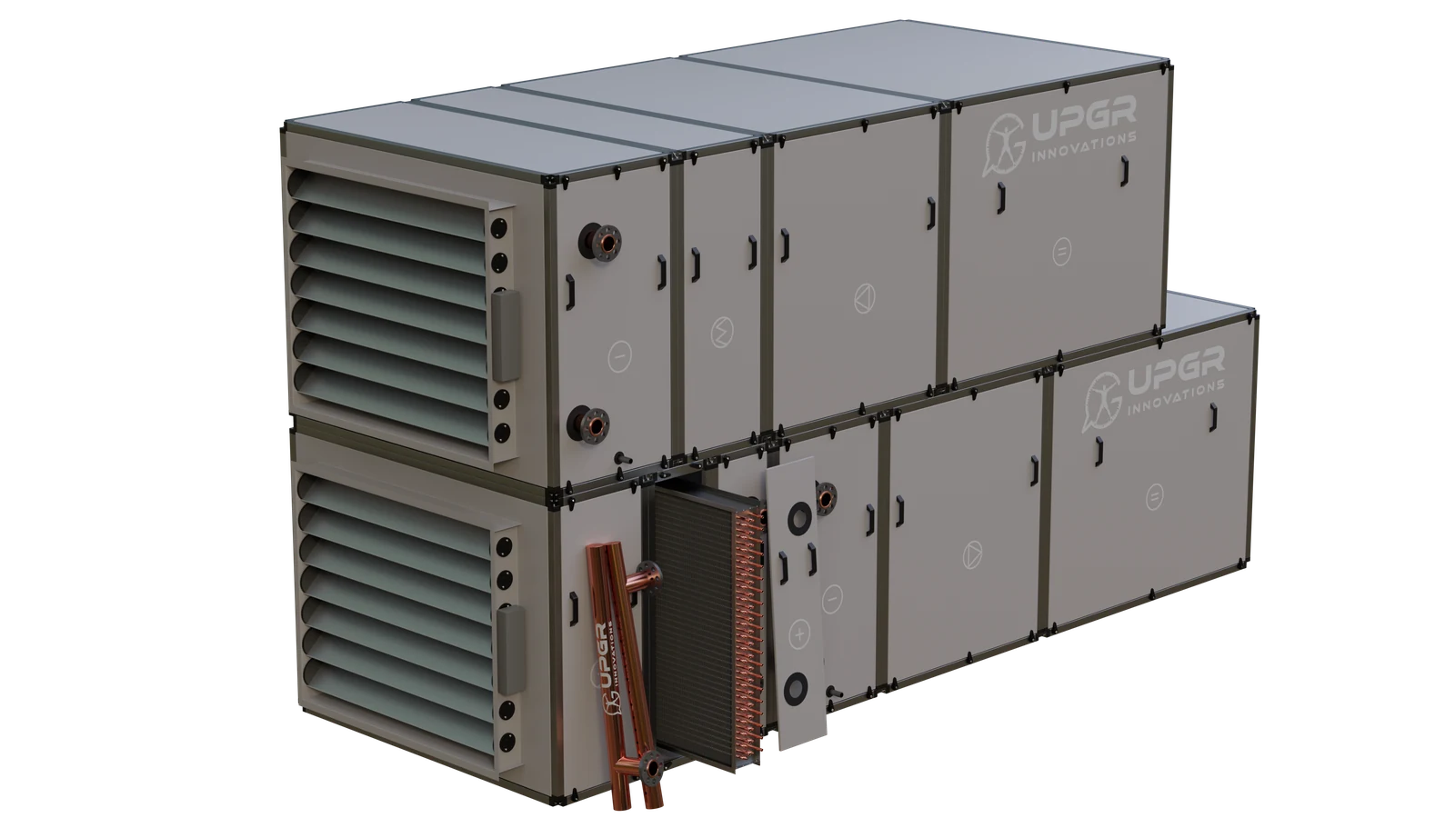
Supply AHUs can heat or cool incoming air using water, glycol or refrigerant coils. Heating and cooling may use separate sections; a wet cooler includes condensate management appropriate to the airflow.
Read the following parts as a typical CuAl coil anatomy. Actual circuiting and accessories vary with the equipment and duty.
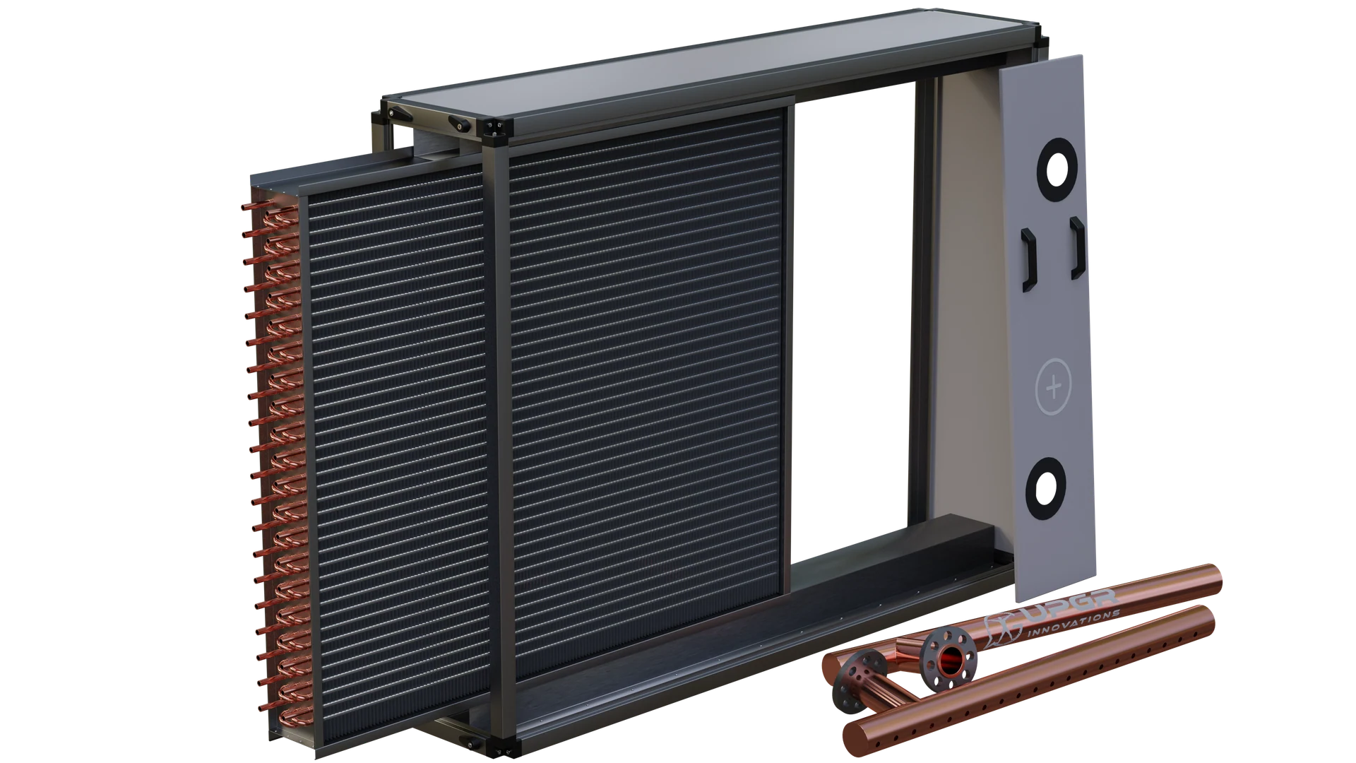
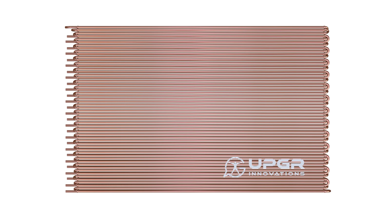
Heat-transfer core
Channels carrying the working fluid through the finned core.
Separate the fluid from air and conduct heat to or from the fins.
Core element of a CuAl finned-tube coil.
Leak traces, corrosion or visible damage.
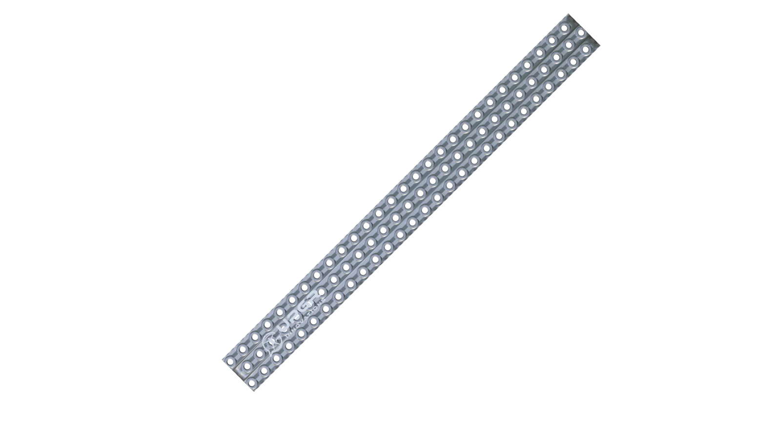
Heat-transfer core
Thin metal sheets in thermal contact with the tubes.
Enlarge the surface exchanging heat with air.
Core element; spacing and profile vary.
Dirt deposits, damaged passages or corrosion.
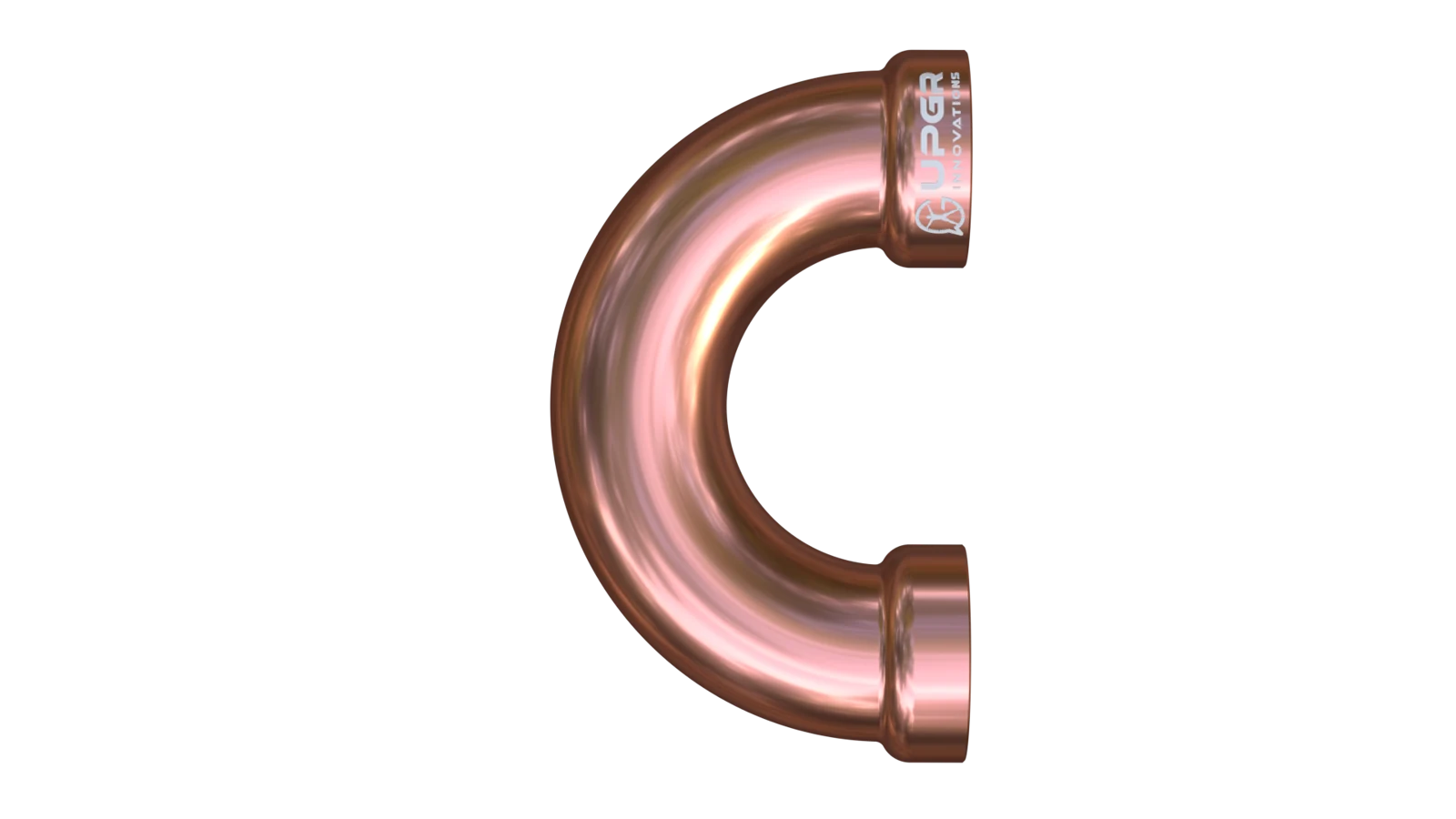
Depends on circuit and construction
Curved tube sections connecting successive passes.
Turn the flow and form the coil circuit.
Layout-dependent; an integral hairpin and a separate return bend are different constructions.
Damaged bends or leakage at joints.
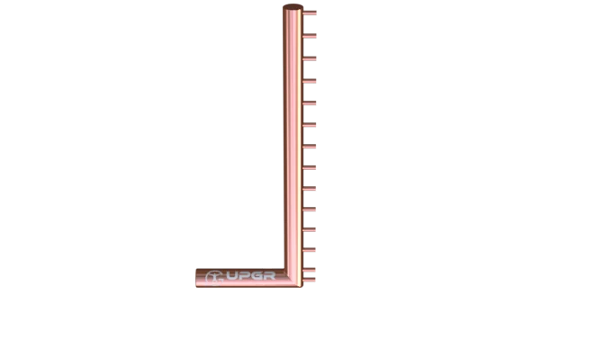
Depends on circuit and construction
Manifolds linking multiple tube circuits to external connections.
Distribute or collect the working fluid.
Arrangement depends on circuiting; headers are not identical to a DX distributor.
Corrosion, joint damage or leak traces.

Depends on circuit and construction
End plates and supporting casing around the core.
Support the core and provide mounting interfaces.
Common; casing styles include end-plates-only constructions.
Deformation, corrosion or damaged mountings.
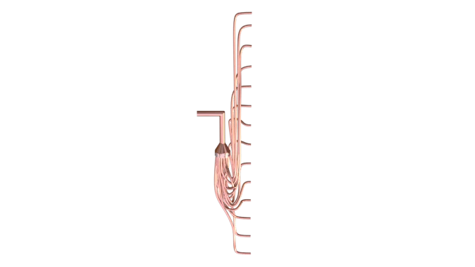
Where required by the duty
A device feeding the parallel circuits of a DX evaporator.
Divides refrigerant between the selected coil circuits.
DX-specific where used; the expansion valve has a separate function.
Damaged small tubes or leakage signs require diagnosis.
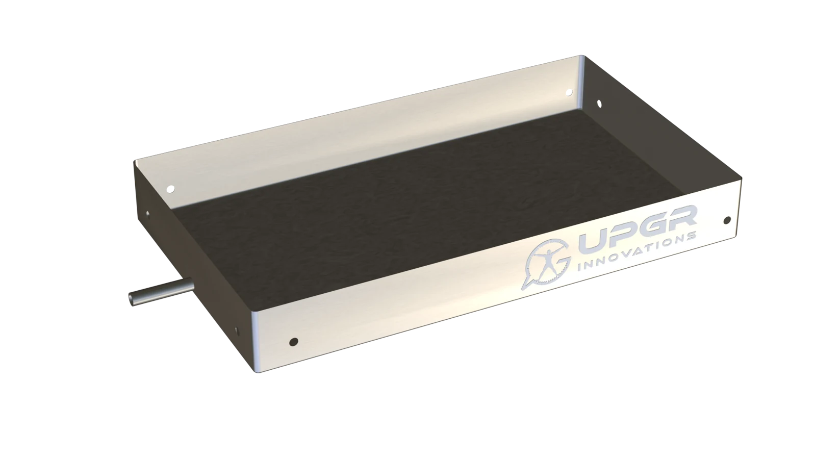
Where required by the duty
A collection surface beneath a coil that produces condensate.
Collect and remove condensed water.
Needed for wet cooling; often part of the equipment section.
Standing water, deposits, corrosion or leakage.
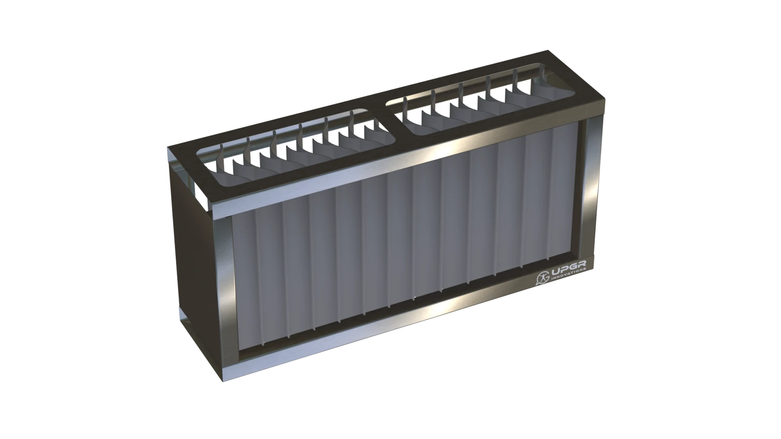
Where required by the duty
A downstream separator for droplets carried by the airflow.
Intercepts droplets and lets collected water drain.
Conditional on carryover risk and equipment design; not every cooling coil has one.
Contamination, damage or water carryover.
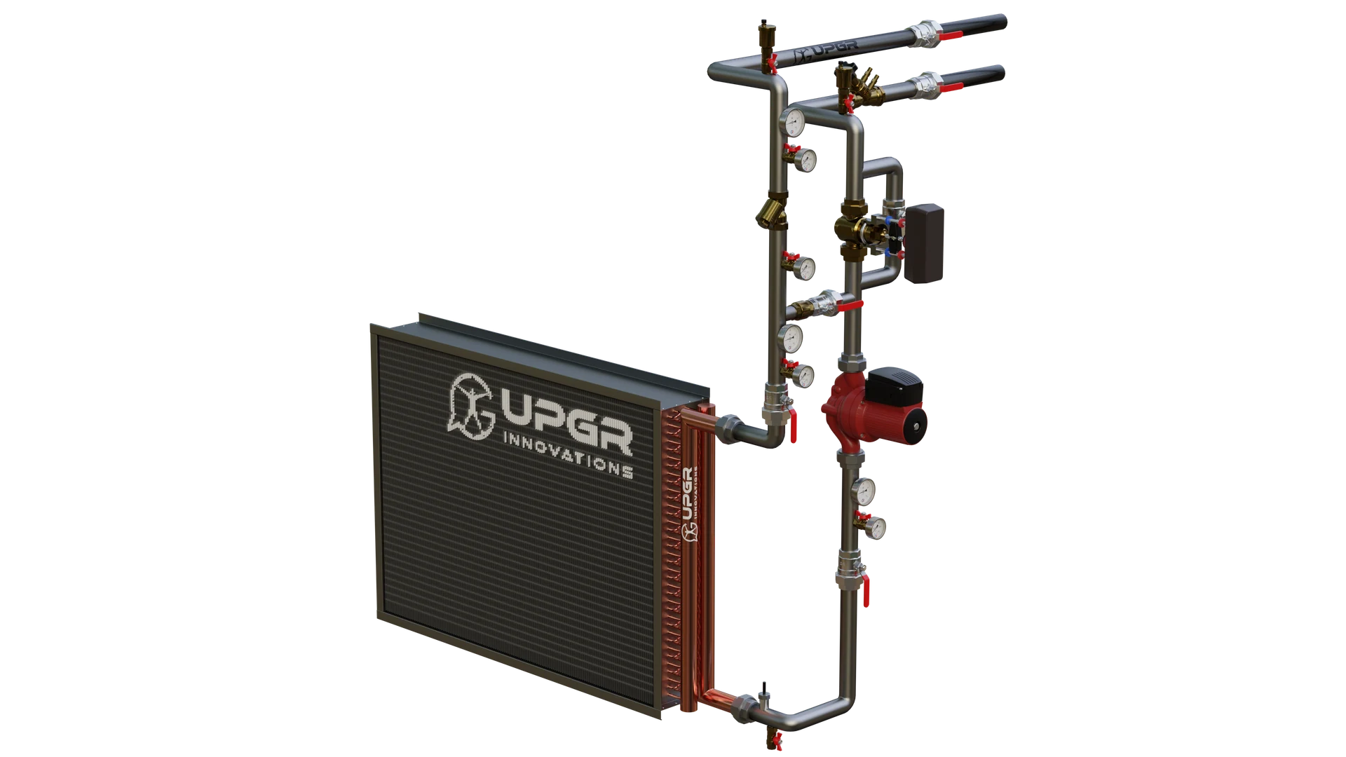
External piping
A separate piping package with valves and, where specified, a pump.
Controls fluid delivery and connects the coil to the system.
External to the finned core; component list follows the circuit design.
Leaks or control faults are system issues, not proof of coil damage.
Condition signs help identify what needs inspection; they do not identify the fault by themselves. Service methods and intervals follow the equipment manual.
A supply air unit may treat outdoor air, mixed air or air leaving heat recovery. The coil's entering temperature therefore need not equal the outdoor temperature. Show the order of any filter, heat-recovery device, heater and cooler, and mark the section concerned.
IN PRACTICE
Two archive service illustrations show the relation between the casing, coil and removable components.
The opened side exposes the coil and its connection area.
The partially withdrawn view makes access relevant; actual clearance and temporary supports require checking.
Confirm the frame, seals and connections for the real unit.
Service access depends on the casing, connection side and available clearance around the unit.
Heating requires the entering air condition and available fluid temperatures. Cooling additionally requires humidity and any dehumidification target. A water coil and a DX coil need different working-fluid data. Several seasonal duties should not be reduced to one capacity value without their operating conditions.
Distinguish fin-pack dimensions, the outer frame and the casing opening. On one defined view, mark airflow, connection side, fixings and the coil-removal route. For a cooler, include the drain pan and drainage. These details make the supply-coil enquiry more specific than the general AHU designation.
The coil check includes allowable air and fluid pressure drops and coordination with piping and controls. Outdoor-air treatment also needs an explicit winter duty and freeze-protection response. A pump, valve or sensor belongs to the supply only when included in the agreed arrangement and component list.
REVIEW THE RESULT
Tie temperature, humidity and airflow to the coil location after any mixing or recovery. Document winter and summer duties separately; outdoor temperature is not always the coil entering temperature.
Compare all three sets of dimensions and connection positions on one agreed view. Define the connection side relative to the shown airflow direction and separately check the space needed to remove the coil.
Agree the drain pan and drainage for a cooler, and winter duty and protection response for a water heater. Check pressure drops and the piping scope for the selected function without inferring supplied components from an image.
SELECTION INPUTS
Define operating conditions first. The input checklist above describes the data needed for this application. The enquiry form adapts to the selected duty; it does not calculate a coil rating.
Add the equipment nameplate, photographs, overall and finned dimensions, airflow direction, connections and access constraints. Matching the envelope alone does not confirm performance or compatibility.
Separate fixed interfaces from dimensions open to change. Attach the current drawing revision, duty points, material requirements, quantity and acceptance criteria. Manufacturing feasibility is confirmed for the specific specification.
Final performance, materials and compatibility require a project-specific selection and an approved drawing.
Only if the air has not been conditioned upstream. Air mixing or heat recovery changes the entering condition, so the actual unit arrangement is needed.
The frame defines the mounting envelope; the fin pack is the active heat-transfer section. Matching one set of dimensions does not establish both installation fit and thermal performance.
It is a separate scope item. State whether the enquiry covers the coil alone, a piping assembly or compatibility with existing equipment.