Specify the air duty, working fluid and installation constraints. Compare alternatives at the same conditions and request a selection sheet together with a drawing of the selected configuration.
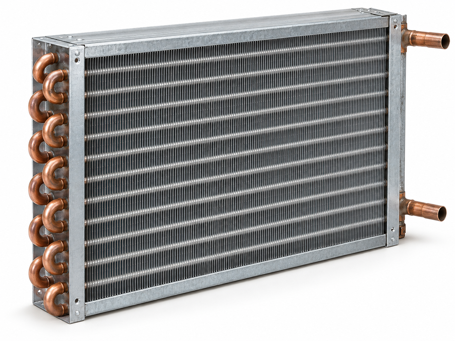
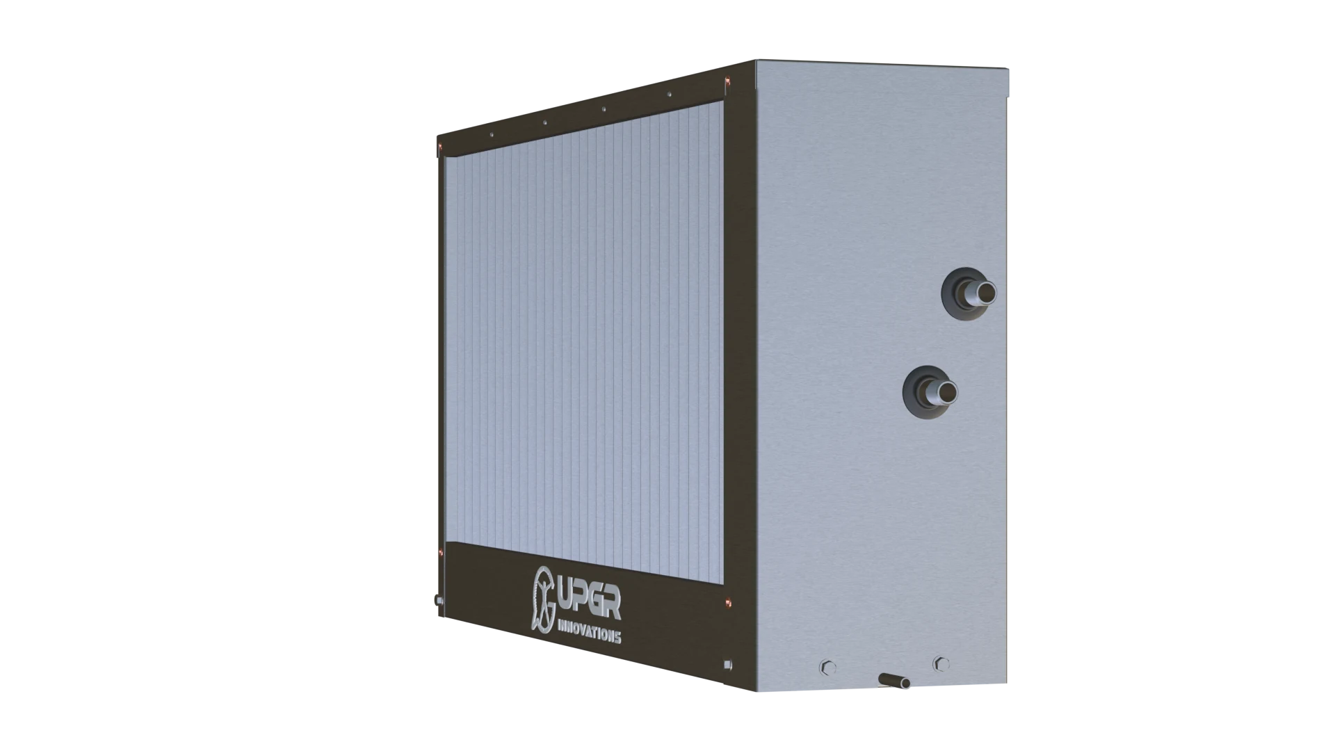
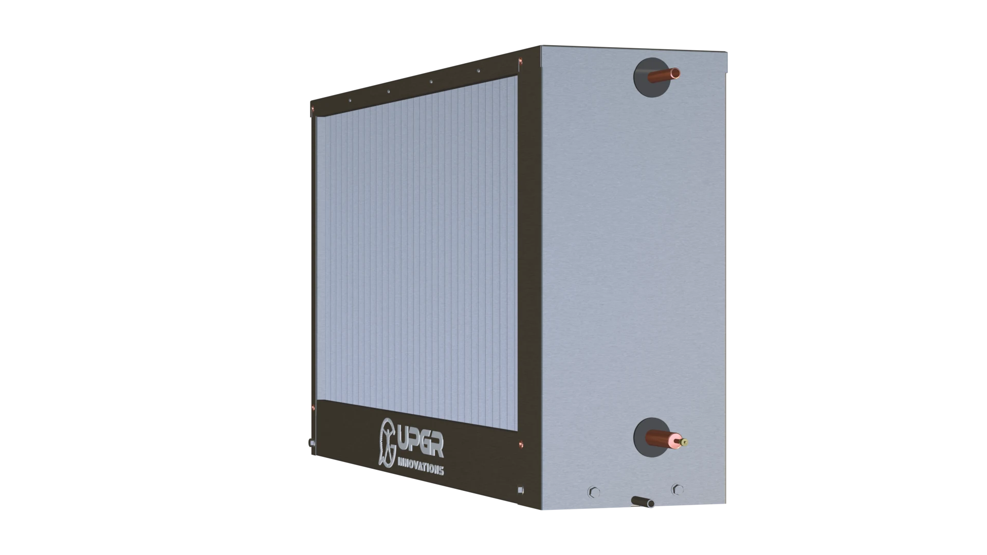
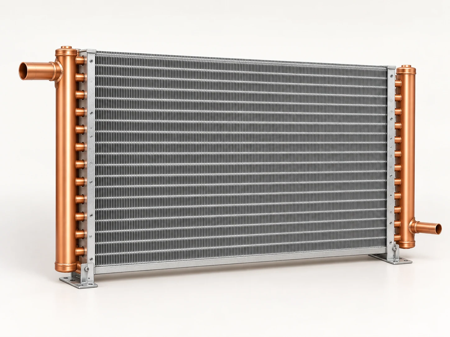
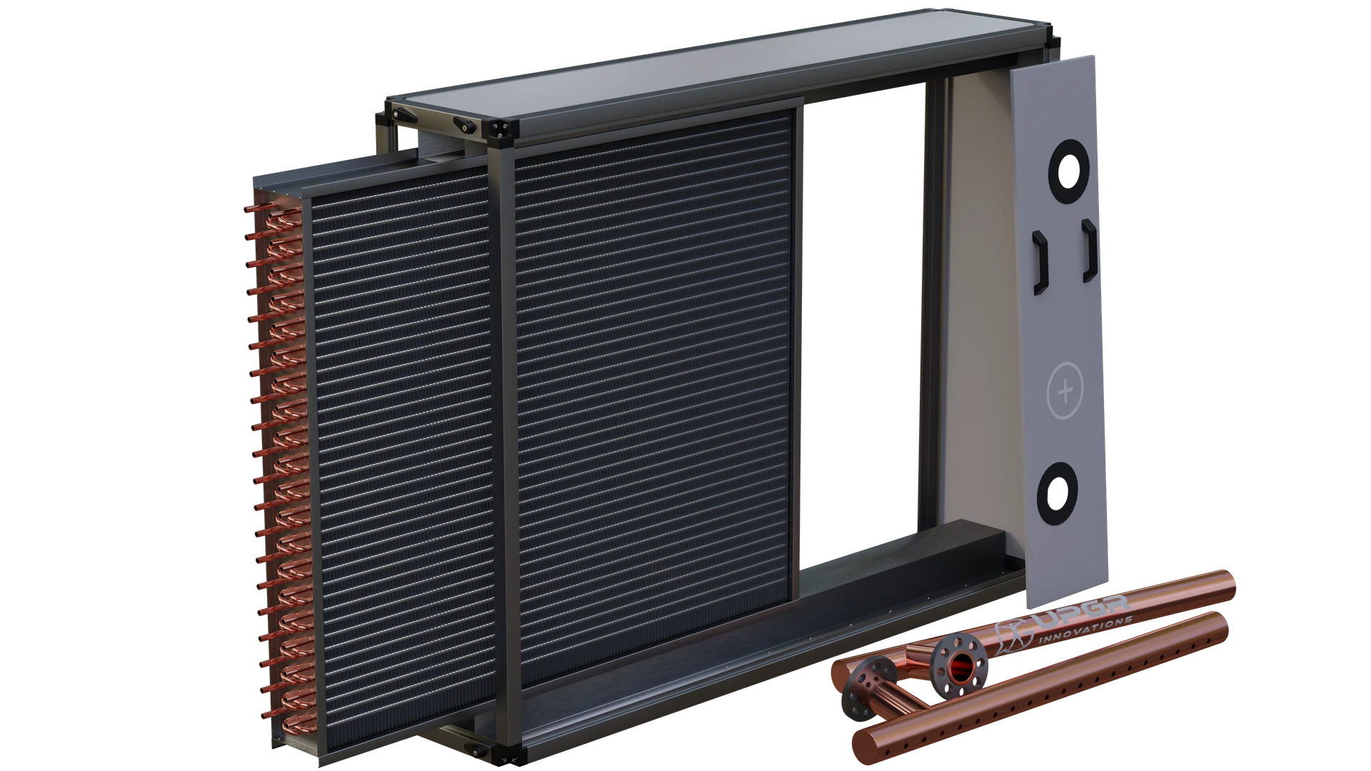
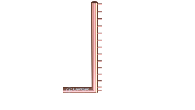
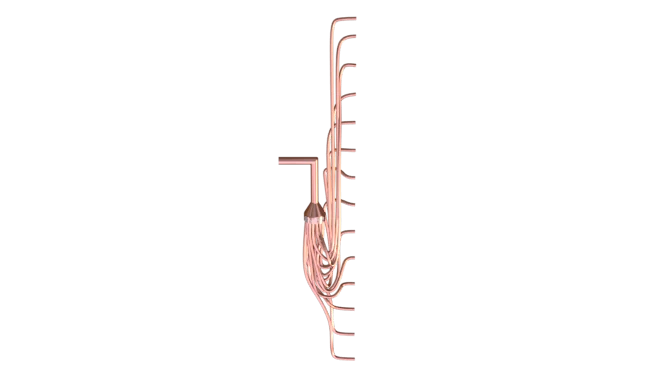
Illustrative liquid-to-air coil. The finned face, return bends and connections are shown; project dimensions, fluid and internal circuits are specified during selection. Owned UPGR archive 3D visualization of КВО 100-50. The view shows the exterior of a water cooling coil; internal circuits, operating conditions and the ordered configuration are defined during selection. Owned UPGR archive 3D visualization of КФО 100-50. The view shows the exterior of a refrigerant cooling coil; internal circuits, operating conditions and the ordered configuration are defined during selection. Generated concept of one air-condenser coil section. Headers and geometry are illustrative; a complete condensing unit and its refrigerant circuit are not shown.
Inside the heat exchanger
Coil selection connects air conditions, fluid conditions, capacity and allowable pressure drops with the available space. Rows and fin spacing describe construction; neither alone states the capacity.
Read the following parts as a typical CuAl coil anatomy. Actual circuiting and accessories vary with the equipment and duty.
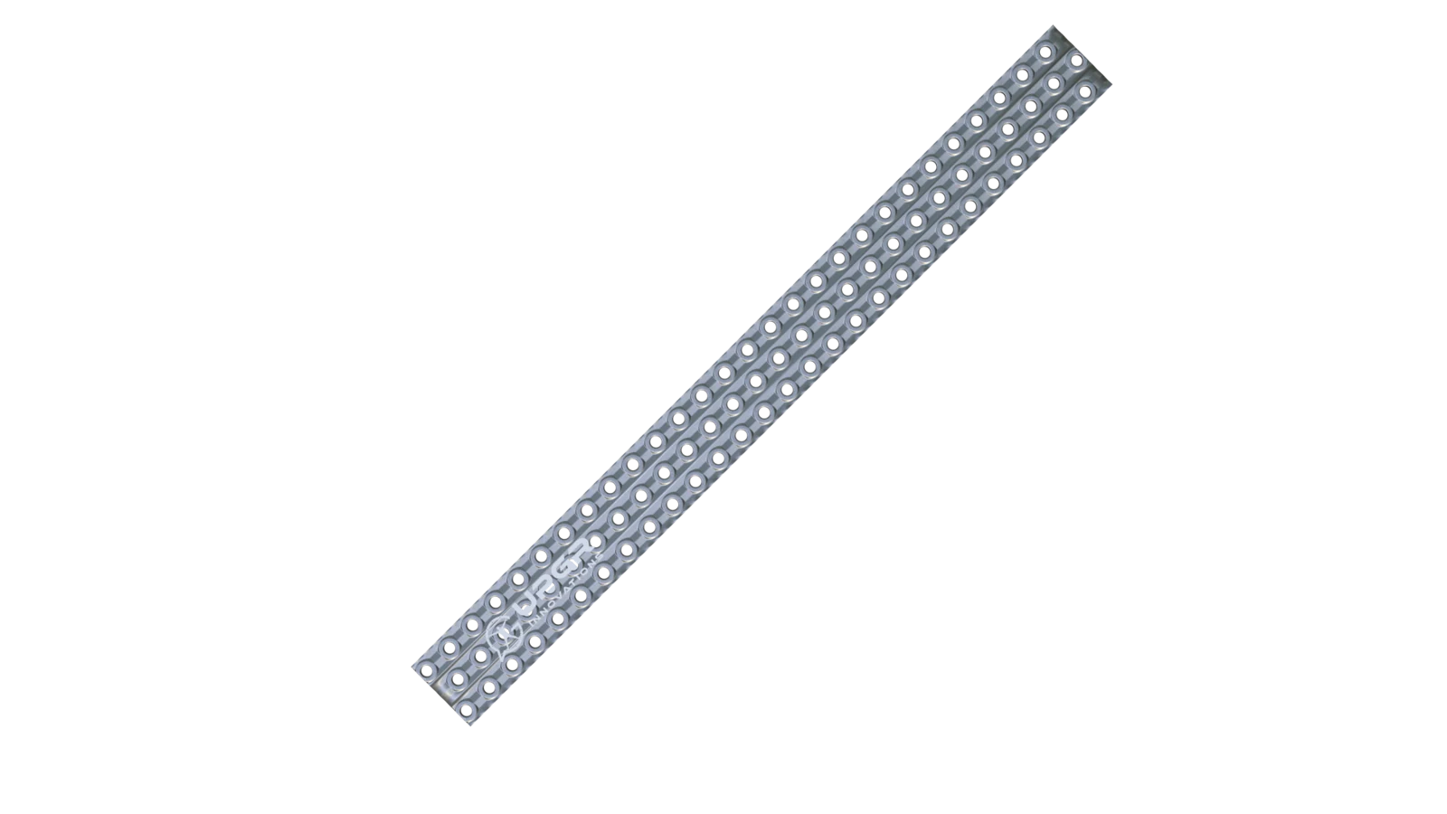
Open a larger image: Exploded view of a finned-tube section. Individual parts below illustrate their function; their dimensions and arrangement vary between coil designs.
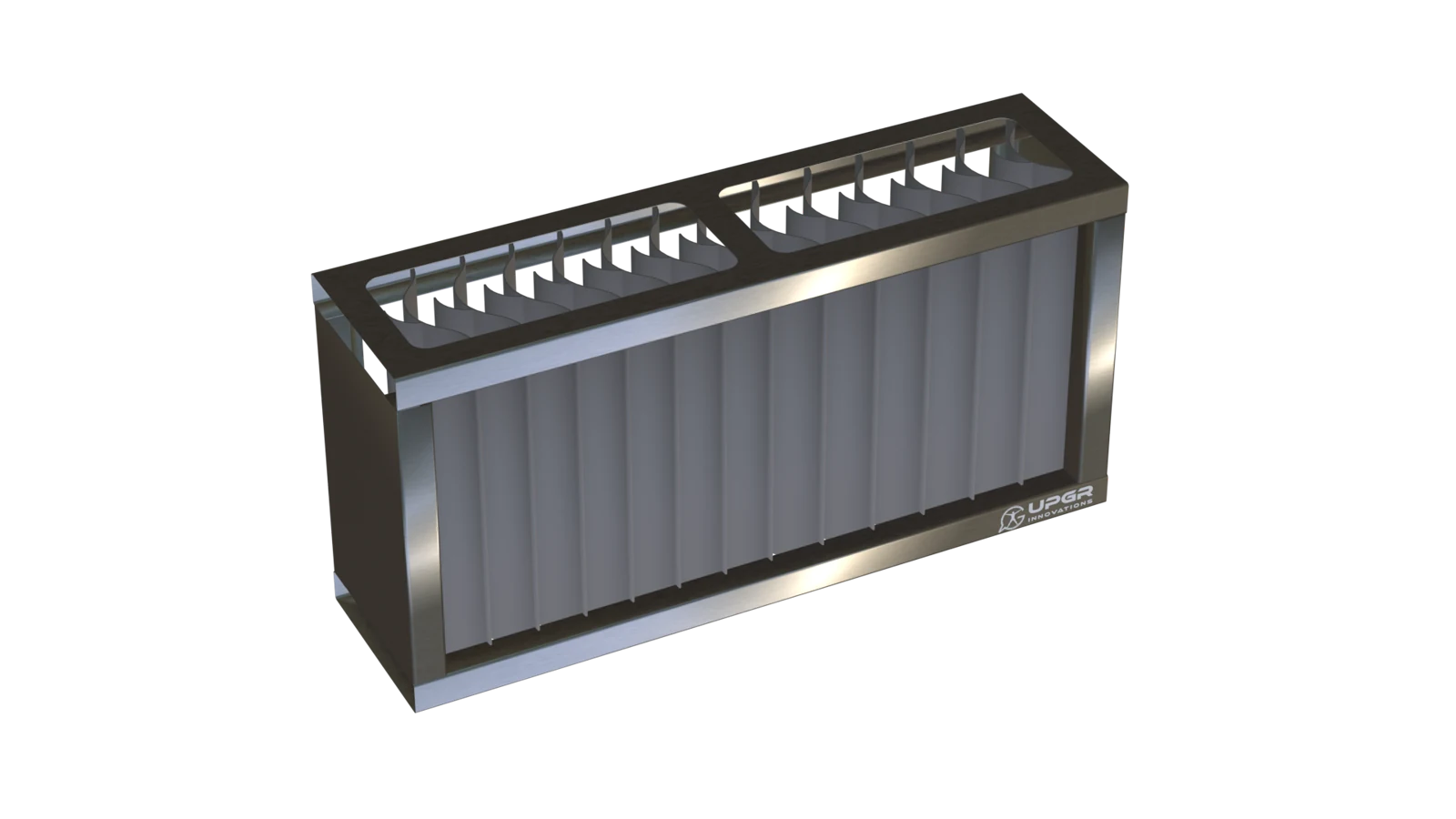
A downstream separator for droplets carried by the airflow.
Intercepts droplets and lets collected water drain.
Conditional on carryover risk and equipment design; not every cooling coil has one.
What to inspect
Contamination, damage or water carryover.
Condition signs help identify what needs inspection; they do not identify the fault by themselves. Service methods and intervals follow the equipment manual.
01
Selection and rating of a defined coil
In selection, the starting point is the required duty and constraints; a suitable construction still needs to be established. In rating, the construction is defined and its performance is assessed under stated conditions. Having only an external view or overall dimensions does not mean the internal geometry is sufficiently defined for a calculation.
02
Both sides of the heat exchanger and their constraints
Describe the air side using airflow and air condition; humidity is particularly important for cooling. Define the other side through its working medium and operating conditions. Available space, connections and pressure-drop limits constrain the choice. A required capacity is useful, but without related conditions it neither defines one unique coil nor establishes installation suitability.
IN PRACTICE
Start with both sides of the duty
A target capacity alone is not enough. The same duty can require different surfaces under different operating conditions.
01
Air
Flow, inlet condition, target outlet and allowable pressure drop.
02
Water / refrigerant
Medium, temperatures or refrigeration conditions, flow constraints.
03
Installation
Available space, connections, materials and service access.
This guide prepares input data. It does not produce a thermal rating or replace manufacturer selection.
03
Unknown inputs and the expected result
Link each parameter to a drawing, specification, measurement or project requirement. Leave unknown fields unknown and mark assumptions explicitly. Define the next-stage outcome in advance: clarification of inputs, assessment of a defined construction or selection of a proposal. Changing page settings assembles task context; it does not confirm a calculation or submission of an enquiry.
REVIEW THE RESULT
What the selection result should contain
New or specified construction
For a new selection, define the required duty and constraints. To rate an existing coil, provide its construction data; if these are incomplete, the first expected result is a clarification list rather than a confirmed capacity.
Comparable alternatives
Compare alternatives using the same input conditions and units. Show the resulting air condition, heat duty, pressure drops and dimensions, and identify every change to the input duty separately.
Selection linked to the drawing
Request the selected configuration identity and the source of the performance data. The selection sheet, dimensional drawing and proposal should refer to the same configuration, with assumptions and unresolved questions kept visible.
Standard sizes, drawings and model cards
Compare the recovered series by nominal opening, frame and casing depth. Each model has its own drawing and render; final suitability depends on the operating duty and connections.
Objective: a new coil, assessment of a defined construction or replacement.
Function, airflow and entering/required leaving air conditions.
Working medium and available temperatures or operating conditions.
Space, connection and pressure-drop constraints.
For rating: an identified construction and supporting documentation.
The source of each value, unknown inputs and the expected outcome.
What do you need to do?
Select a new coil
Define operating conditions first. The input checklist above describes the data needed for this application. The enquiry form adapts to the selected duty; it does not calculate a coil rating.
Add the equipment nameplate, photographs, overall and finned dimensions, airflow direction, connections and access constraints. Matching the envelope alone does not confirm performance or compatibility.
Separate fixed interfaces from dimensions open to change. Attach the current drawing revision, duty points, material requirements, quantity and acceptance criteria. Manufacturing feasibility is confirmed for the specific specification.
Final performance, materials and compatibility require a project-specific selection and an approved drawing.
Questions about this application
How does rating differ from selection?
They are two ways to define the engineering task. First state whether the construction is already defined or still needs to be selected, then use the corresponding input set.
If the required capacity is known, are other inputs still needed?
Capacity does not describe every heat transfer condition. Assessment requires the related operating conditions and constraints; without them, a particular geometry cannot be considered justified.
Can an enquiry start when some parameters are unknown?
Yes. Available documents and the enquiry objective can establish a list of clarifications. Keep missing values explicit; a prepared enquiry must not be presented as a final calculation or confirmed selection.