Multi-split outdoor coil
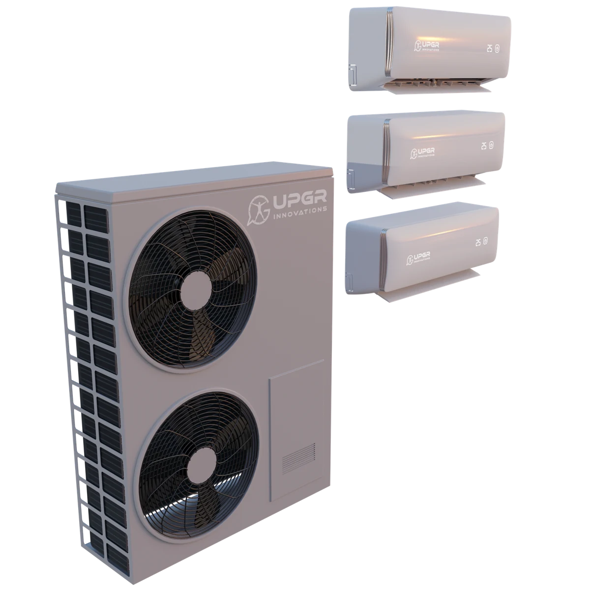
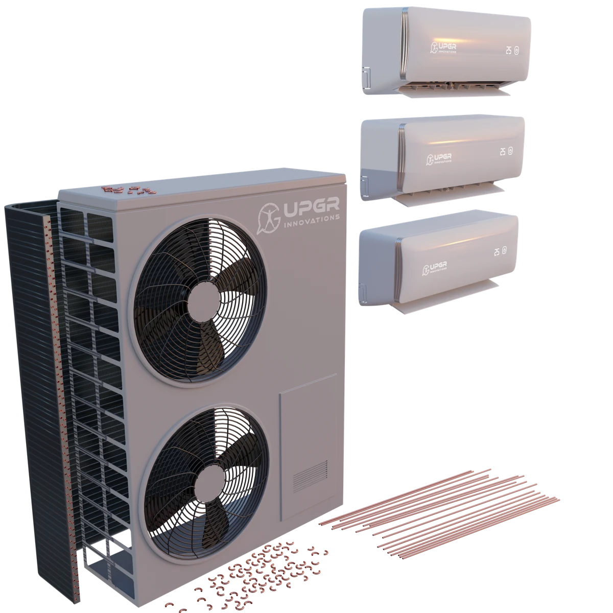
Multiple indoor units share an outdoor unit. The exploded view separates the finned core, tubes and return bends; compatibility depends on the entire refrigerant system.
By equipment
For a system with several indoor units, identify the shared outdoor unit, list the connected units and mark the branch containing the replacement coil. The review must cover that complete combination. For one matched pair, use the single-split guide.
Compare the complete unit, access to the coil and an exploded view. These examples show the relationship between the equipment casing and the heat-transfer section.
Multiple indoor units share an outdoor unit. The exploded view separates the finned core, tubes and return bends; compatibility depends on the entire refrigerant system.
A multi-split connects several indoor units to shared outdoor equipment. Identify the branch and the complete permitted combination; the size of one coil cannot establish compatibility with the whole refrigerant system.
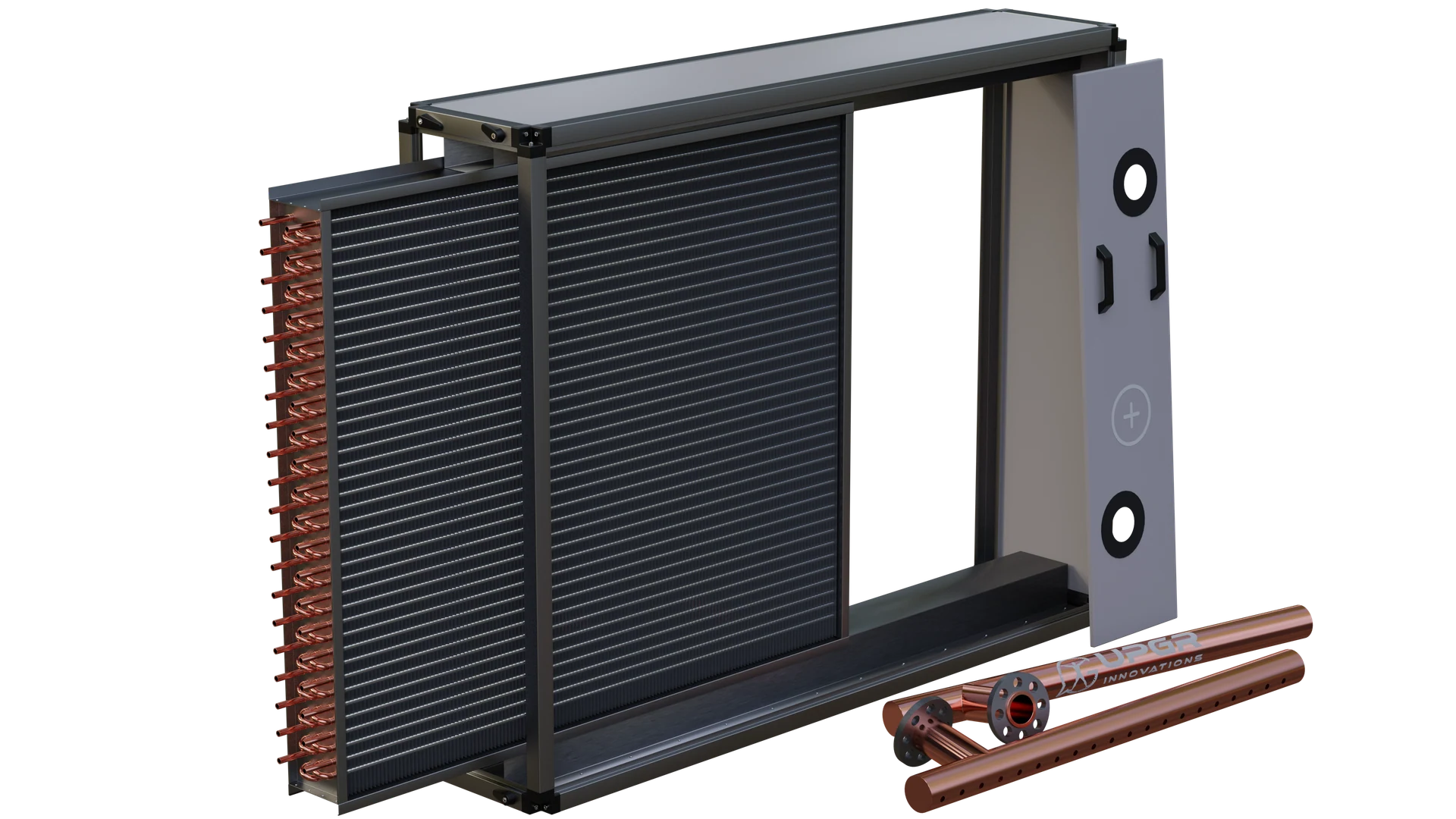
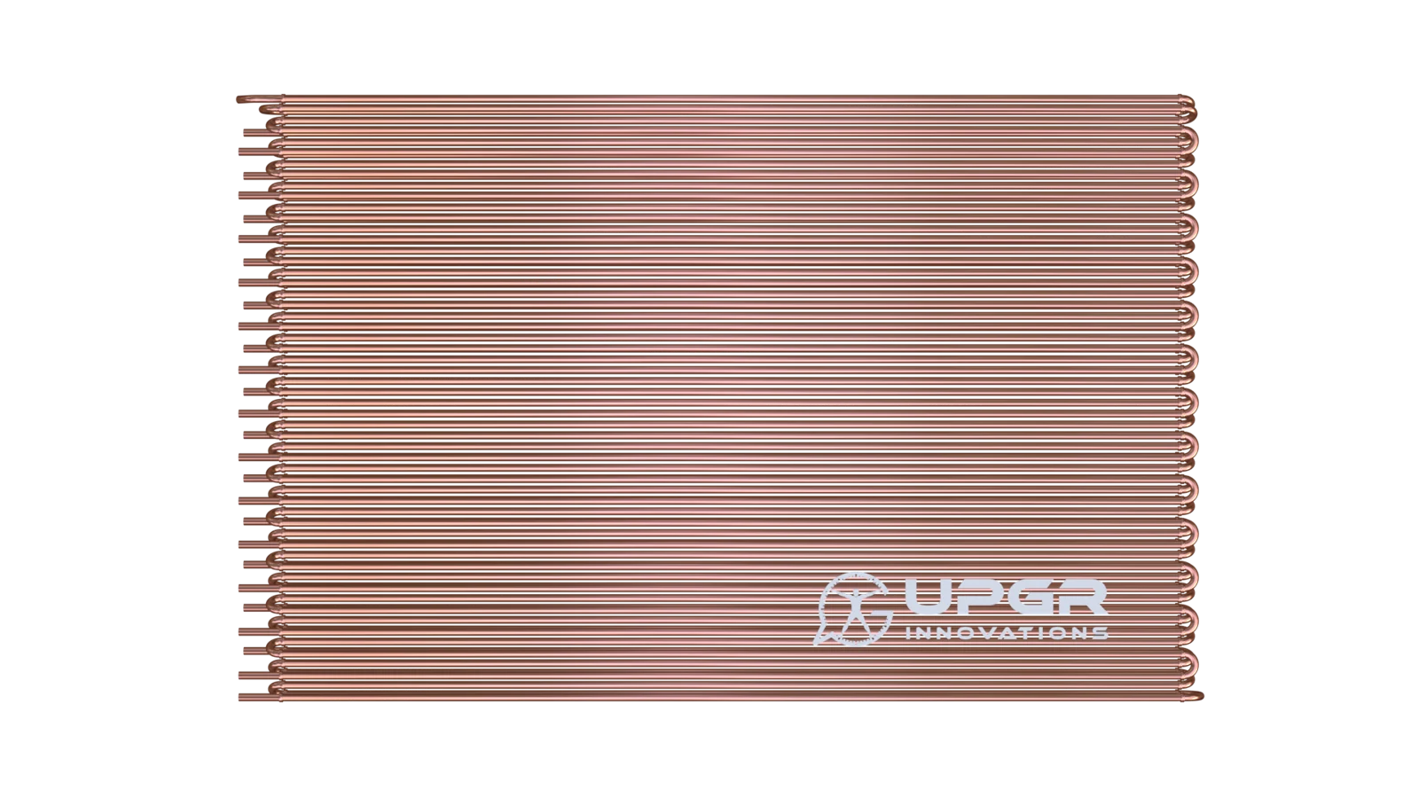
Read the following parts as a typical CuAl coil anatomy. Actual circuiting and accessories vary with the equipment and duty.
Heat-transfer core
Channels carrying the working fluid through the finned core.
Separate the fluid from air and conduct heat to or from the fins.
Core element of a CuAl finned-tube coil.
Leak traces, corrosion or visible damage.
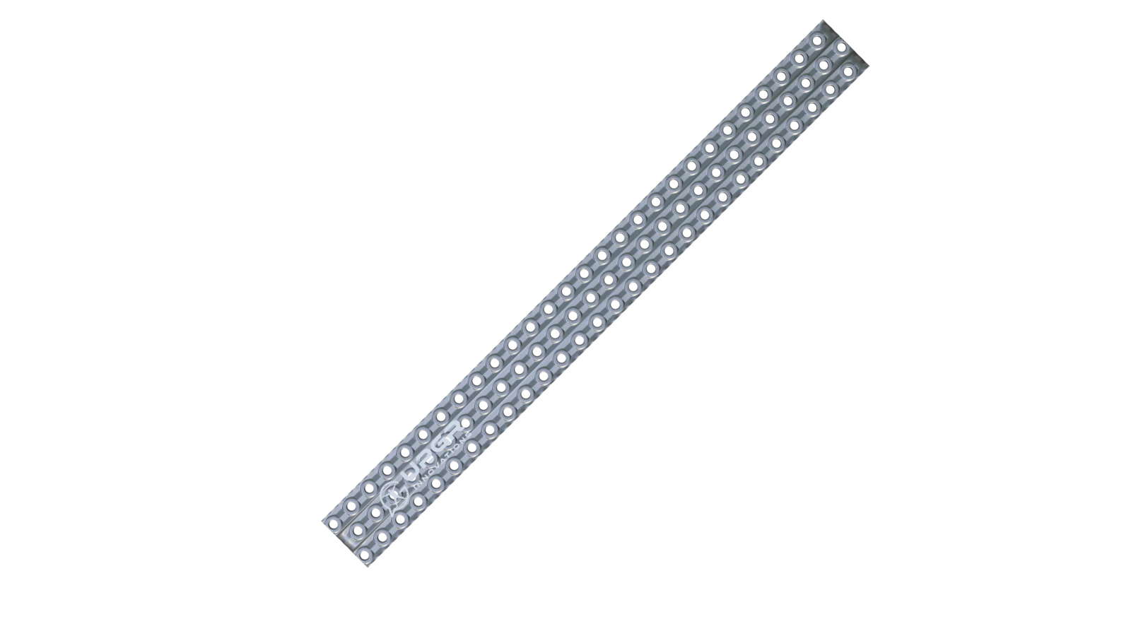
Heat-transfer core
Thin metal sheets in thermal contact with the tubes.
Enlarge the surface exchanging heat with air.
Core element; spacing and profile vary.
Dirt deposits, damaged passages or corrosion.
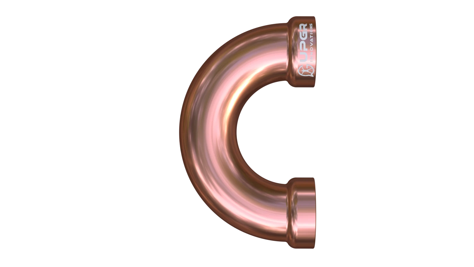
Depends on circuit and construction
Curved tube sections connecting successive passes.
Turn the flow and form the coil circuit.
Layout-dependent; an integral hairpin and a separate return bend are different constructions.
Damaged bends or leakage at joints.
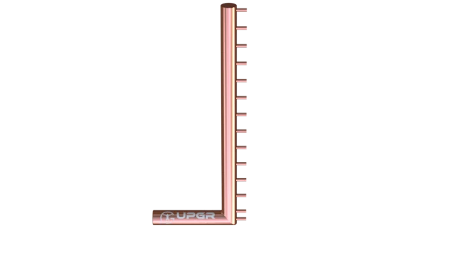
Depends on circuit and construction
Manifolds linking multiple tube circuits to external connections.
Distribute or collect the working fluid.
Arrangement depends on circuiting; headers are not identical to a DX distributor.
Corrosion, joint damage or leak traces.

Depends on circuit and construction
End plates and supporting casing around the core.
Support the core and provide mounting interfaces.
Common; casing styles include end-plates-only constructions.
Deformation, corrosion or damaged mountings.
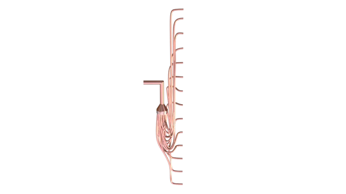
Where required by the duty
A device feeding the parallel circuits of a DX evaporator.
Divides refrigerant between the selected coil circuits.
DX-specific where used; the expansion valve has a separate function.
Damaged small tubes or leakage signs require diagnosis.
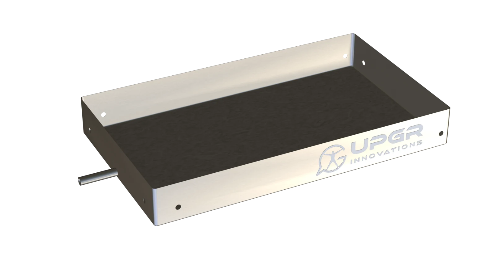
Where required by the duty
A collection surface beneath a coil that produces condensate.
Collect and remove condensed water.
Needed for wet cooling; often part of the equipment section.
Standing water, deposits, corrosion or leakage.
Condition signs help identify what needs inspection; they do not identify the fault by themselves. Service methods and intervals follow the equipment manual.
Several indoor units may connect to one outdoor unit. Identify whether the replacement concerns one indoor branch or the shared outdoor coil. The outdoor unit's total capacity does not define each room's heat exchanger or its connections.
IN PRACTICE
The archive example shows three indoor units alongside one outdoor unit. The actual combination is defined by the project.
List the outdoor model and each connected indoor model.
State the exact unit and section that needs selection or replacement.
Use the manufacturer documentation to confirm the permitted combination and refrigerant circuit.
Three indoor units are shown as a presentation example; the image is not an approved connection diagram.
Retain the model list and branch diagram, including any specified distribution components. Check permitted unit combinations, pipework and refrigerant metering against the relevant series documentation. A coil with a suitable shape does not automatically become compatible with the shared system.
In a reversible system the coil's function depends on mode, while permitted simultaneous operation of the units depends on the actual arrangement. The term multi-split alone does not establish simultaneous heating and cooling. Record the original limits and required joint operating conditions.
Record refrigerant, branch identity, connections, sensors and coil measurements. For an indoor unit, add drain-pan and fan interfaces; for the outdoor unit, show the shared coil arrangement. Changing coil size or branching is not simply a like-for-like replacement.
REVIEW THE RESULT
Link the replacement coil to its branch or the shared outdoor unit. Retain every model and specified distribution component; one indoor unit's data does not describe the complete system.
Check compatibility using documentation for this exact series: models, branch roles, pipework limits and controls. The sum of nominal capacities is not a substitute for a permitted combination.
Record available modes and the rules for units operating together. Tie coil function to the selected mode; simultaneous heating and cooling must be established by the actual system design, not the multi-split label.
SELECTION INPUTS
Define operating conditions first. The input checklist above describes the data needed for this application. The enquiry form adapts to the selected duty; it does not calculate a coil rating.
Add the equipment nameplate, photographs, overall and finned dimensions, airflow direction, connections and access constraints. Matching the envelope alone does not confirm performance or compatibility.
Separate fixed interfaces from dimensions open to change. Attach the current drawing revision, duty points, material requirements, quantity and acceptance criteria. Manufacturing feasibility is confirmed for the specific specification.
Final performance, materials and compatibility require a project-specific selection and an approved drawing.
A shared outdoor unit links the branches. Replacement must account for compatibility and limits of the complete system, not just one indoor unit.
No. Permitted models and combinations must be checked against the manufacturer's documentation for that series. Matching brand or total nominal capacities is insufficient.
No. That capability depends on the design and circuit arrangement. It cannot be transferred from another system or inferred from the number of indoor units.